


D9412GV2/D7412GV2 | Operation and Installation Guide | 4.0 Installation
18 Bosch Security Systems, Inc. | 5/05 | F01U003641B
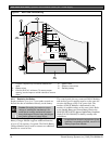
4.6 Completing the Installation
If not already complete, make the earth ground
connection to Terminal 10 and lock the reset pin in the
closed position.
4.6.1 Charging the Battery
Connect the battery, then the transformer to allow the
control panel to charge the battery while you complete
the installation. Refer to Section 5.0 Power Supply on
page 20 for instructions.
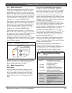
On-board Buzzer Sounds at Power Up and Reset:
The system performs a series of self-diagnostic tests of
hardware, software, and programming at power up and
at reset. The buzzer on the control panel sounds during
the tests. The self-diagnostics tests complete in
approximately 1 to 3 seconds.
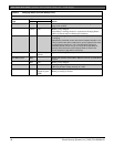
If the control panel fails any test, the buzzer continues
sounding and a System Trouble message appears at the
keypads. Refer to Problems Found during Self Diagnostics
in the D9412GV2/D7412GV2/D7212GV2 Installation and
Troubleshooting Quick Reference Guide (P/N: F01U003638)
for a description of each system trouble message.
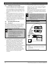
Touch Terminal 10 First: If the on-board buzzer
sounds briefly when the control panel is touched, any
static charge you carry discharges to the control panel.
Avoid electrostatic discharge. Always touch
Terminal 10, the earth ground connection,
before beginning work on the control panel.
If the control panel receives an electrostatic discharge,
it might generate Watchdog Reset and Param
Fail events. Refer to Watchdog Reset Reports in the
D9412GV2/7412G/D7212GV2 Installation and
Troubleshooting Quick Reference Guide
P/N: F01U003638) for a description of these events.
4.6.2 Installing and Wiring Detection Devices
Install and wire detection devices and keypads at their
locations throughout the premises. Do not connect the
control panel yet.
Section 8.0 On-Board Points on page 31 contains
instructions for wiring the on-board points to detection
devices. Section 11.0 Arming Devices on page 53 contains
instructions for wiring the keypads.
Instructions for wiring the off-board point POPIT
sensor loops are found in the instructions packaged
with the POPIT modules.
4.6.3 Installing Modules and Relays
1. Power down the unit by unplugging the
transformer and disconnecting the battery.
Always power down the unit when installing
modules or relays, or when making wiring
connections to the control panel.
2. Install and wire any modules required for the
installation as described in the module’s
installation instructions.
Instructions for the D8125 POPEX Module,
D8128D OctoPOPIT Module, D8129 OctoRelay
Module, D811 Arm Status Relay Module, and
D928 Dual Phone Line Switcher appear in this
guide.
Refer to Section 9.0 Off-Board Points on page 34 for
D8125 and D8128D instructions. Refer to Section
10.0 Off-Board Relays on page 48 for D8129 and
D811 instructions. Refer to Section 7.11 D928 Dual
Phone Line Switcher on page 29 for D928
instructions.
3. If using the power outputs at Terminals 7 or 8,
install a D136 relay in the appropriate sockets.
Refer to Section Programmable Power Output
Terminals 6, 7, and 8 on page 25 for instructions.
4.6.4 Connecting the On-board Points and
Keypads
Connect the on-board points and keypad wiring to the
system. Refer to Section 8.0 On-Board Points on page 31
and Section 11.0 Arming Devices on page 53 for
instructions.
4.6.5 Powering Up
Reconnect the battery, then plug in the transformer.
The buzzer sounds for 2 seconds when the control
panel is powered up. Leave the reset pin in the locked
position.
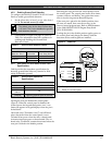
Yellow Charging Status LED Remains Lit: If the
yellow charging status LED remains lit after five
minutes of powering up the control panel, either the
battery is deeply discharged or too many powered
devices were connected to the control panel.
Combined continuous current draw for Terminals 3, 8,
24, and 32, and the accessory connector cannot exceed
1.4 A. Refer to Section 6.0 Power Outputs on page 25 for
help.