


D9412GV2/D7412GV2 | Operation and Installation Guide | 7.0 Telephone Connections
.
Bosch Security Systems, Inc. | 5/05 | F01U003641B 29
7.11 D928 Dual Phone Line Switcher
7.11.1 Description
The optional D928 Dual Phone Line Switcher allows
the control panel to send reports over two separate
telephone lines. The control panel monitors both lines.
If a line generates a signal and the control panel senses
that a line is bad, the control panel attempts to use the
other telephone line to send the message. If trouble is
detected, the control panel keeps the faulty telephone
line in memory.
Set the Ring Count above 2 on Answering
Machines: The control panel’s RPS line monitor
feature might not operate correctly if an answering
machine with a ring count of less than two rings is
connected to a telephone line used by the D928
Module.
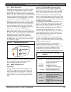
7.11.2 Operation
Refer to Phone in the D9412GV2/D7412GV2 Program
Entry Guide (P/N: F01U003636) for telephone
supervision and reporting options. To use the D928, set
the
Two Phone Lines
prompt to Yes.
When the D928 is installed, the control panel alternates
between Phone Line 1 and Phone Line 2 to send its
first report. For example, on day one, the control panel
first attempts to communicate on Phone Line 1. On
day two, the control panel switches and attempts to
communicate on Phone Line 2.
Any time the control panel resets or is
powered down or up, the next reported event
always attempts to call out on Phone Line 1
first.
If Phone Line 2 is not in service on “Day 2”,
the control panel switches to the primary
phone line to send the report.
With the D928 Dual Phone Line Switcher installed, the
control panel uses two telephone lines (primary and
secondary) to dial up to four telephone numbers.
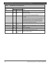
When using a primary and a backup device within a
Route Group #
, the control panel makes two attempts
on the primary telephone line using the
Primary
Device #
as programmed. If these two attempts fail,
the control panel switches to the secondary telephone
line using the
Backup Device #
as programmed. This
pattern continues for a total of ten attempts. After ten
unsuccessful attempts, the control panel generates a
Comm Fail event for the given
Route Group #
.
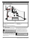
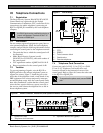
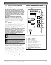
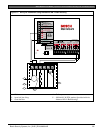
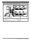
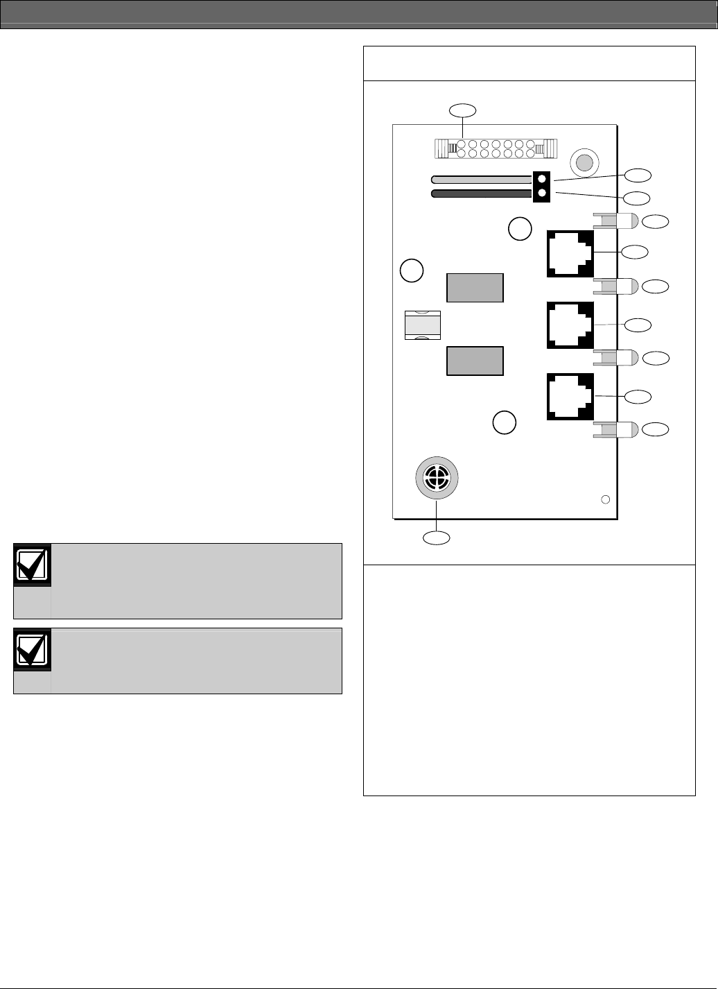
Figure 9: D928 Dual Phone Line Switcher
+
+
4
6
8
10
1
2
3
5
7
9
11
1 - Connect to ACCESSORY CONNECTOR with
ribbon cable.
2 - Green to Terminal 1
3 - Black to Terminal 9
4 - AC Power LED (green)
5 - Phone jack to primary phone line
6 - Primary Fail LED (yellow)
7 - Phone jack to secondary phone line
8 - Secondary Fail LED (yellow)
9 - Phone jack to telco connector
10 - Communications Fail LED (yellow)
11 - Buzzer