


D9412GV2/D7412GV2 | Operation and Installation Guide | 9.0 Off-Board Points
.
Bosch Security Systems, Inc. | 5/05 | F01U003641B 39
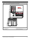
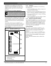
9.3.4 Wiring Data Expansion Loops to POPEX
Modules
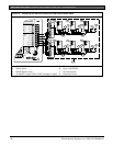
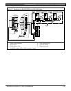
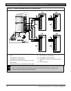
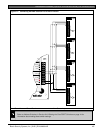
Each POPEX Module has two positive (+) and two
negative (-) data expansion loop terminals. Up to 119
POPITs can be connected to one D8125 on the
D9412GV2; 67 for the D7412GV2 (Figure 12 on page
36 and Figure 13 on page 37.
To connect the data expansion loops to the D8125
POPEX Module:
1. Connect the positive (+) data terminal from the
first POPIT on the data expansion loop to one of
the D8125’s positive (+) terminals.
2. Connect the negative (-) data terminal from the first
POPIT on the data expansion loop to one of the
D8125’s negative (-) terminals.
9.3.5 POPIT Sensor Loops
The number of normally-open and normally-closed
detection devices each sensor loop can supervise is
limited only by the resistance on the loop. Resistance
on each sensor loop must be less than 100 Ω not
including the EOL resistor.
Certain UL and NFPA applications can limit the
number of detection devices. Consult the appropriate
UL or NFPA standards.
POPITs detect open, shorted, normal, and grounded
circuit conditions on their sensor loops. They send the
condition of their loops to the control panel. A ground
on the sensor loop sends a general system ground-fault
condition report. Refer to Ground Fault in the
D9412GV2/D7412GV2/D7212GV2 Installation and
Troubleshooting Quick Reference Guide
(P/N: F01U003638). Each POPIT is programmed and
sends signals to the control panel separately.
Terminate each POPIT sensor loop with the 33 kΩ
EOL resistor (D106F) included with each POPIT.
Use a twisted-pair wire (six twists per foot) in all
POPEX and POPIT installations for both the data
expansion loop wiring and the POPIT sensor loops.
Run wires away from AC sources to prevent AC
induction. If a noisy environment is suspected, use
shielded cable. Refer to Section 9.3 Installing the D8125
POPEX Module on page 38.
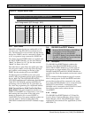
9.3.6 POPIT Module Point Assignments
Six switches on each POPIT assign the module to a
point number. For POPIT switch settings, refer to Point
Assignment in the D9412GV2/D7412GV2 Program Record
Sheet (P/N: F01U003635). The program record sheet
provides information about the Point Assignments
tables. Figure 14 on page 40 is an example of the tables.
For the D9412GV2, Points 73 to 127 and
193 to 247 must use the D9127 POPITs.
Points 9 to 72 and 129 to 192 can use
either D8127 or D9127 POPITs.
For the D7412GV2, Points 9 to 72 can use
either D8127 or D9127 POPITs; however,
D9127 POPITs must be used for Points 73
to 75.
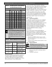
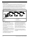
9.3.7 Program Record Sheet
The first column of the table in Figure 14 on page 40
contains the POPIT Switch Settings for the D8127
POPITs. On the D8127 POPITs, the switches are
numbered 1 to 6, from left to right. On the D9127
POPIT, switches are numbered 0 to 6, from left to
right. Set the indicated switches to the ON position. If a
dash (−) appears in the switch position, set the switch to
the OFF position.
The second column contains the Translation of the
point number into the Zonex format. Refer to Point
User Flag in the D9412GV2/D7412GV2 Program Entry
Guide (P/N: F01U003636) for an explanation of this
feature.
The third column contains the Point Number as
shown at keypads.
The fourth column contains the Point Index. Refer to
Point Index Parameters in the D9412GV2/D7412GV2
Program Entry Guide (P/N: F01U003636)for an
explanation of the point index.
The fifth column, Area Assign, shows the area to
which the point is assigned.
The sixth column shows the Debounce Count for the
point. Refer to Debounce Count in the
D9412GV2/D7412GV2 Program Entry Guide
(P/N: F01U003636).
The seventh column shows the BFSK/Relay report
code, which is the point number reported for this point
when the control panel is using the BFSK format.
The eighth column contains the Custom Point Text
displayed at keypads for the point. The text is sent to
the receiver when the control panel uses the Modem
IIIa
2
format.