


D9412GV2/D7412GV2 | Operation and Installation Guide | 9.0 Off-Board Points
.
Bosch Security Systems, Inc. | 5/05 | F01U003641B 41
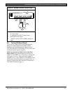
The D8128D is also suitable for fire supervisory
applications, such as indicating circuit supervision
(using the D192C/D192G Bell Circuit Supervision
Module), sprinkler supervision, and valve tamper
protection.
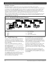
Requirements for Fire Initiation Applications
Non-powered, fire initiating devices such as
pull-stations, heat detectors, and UL Listed
four-wire smoke detectors can be connected
directly to the point inputs on the D8128D.
The D125B Dual Powered Loop Interface Module or
the D129 Dual Class “A” Module zone outputs can be
connected directly to the point inputs on the D8128D.
Use the D125B to connect two-wire smoke detectors.
Typically, the D129 is used for connecting waterflow
switches.
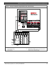
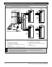
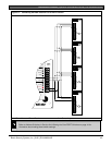
The D125B or D129 and the OctoPOPIT can be
mounted in the same enclosure with the control panel
or in a separate enclosure connected to the control
panel’s enclosure by a conduit not more than 6 m
(20 ft.) in length.
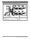
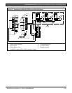
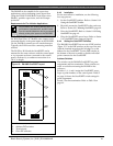
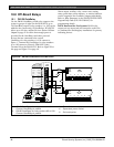
Figure 15: D8128D OctoPOPIT Layout
23451 678
P O I N T S
1
2
3
4
1 - Molex
®
connectors
2 - Address DIP switches
3 - Terminal strip
4 - Point DIP switches
9.4.3 Installation
For the most effective installation, use the following
four-step process:
1. Set the OctoPOPIT switches. Refer to Section 9.4.4
Setting the OctoPOPIT Switches.
2. Physically mount the OctoPOPIT in the enclosure.
Refer to Section 9.4.5 Mounting OctoPOPITs, page 42.
3. Wire the OctoPOPIT. Refer to Section 9.4.6 Wiring
OctoPOPITs on page 42.
4. Wire the OctoPOPIT sensor loops. Refer to Section
9.4.7 OctoPOPIT Sensor Loops on page 46.
9.4.4 Setting the OctoPOPIT Switches
The D8128D OctoPOPIT has two sets of DIP switches
(Figure 15). Use the DIP switches on the top of the unit
(with the terminal strip along the left edge) to set the
address for the OctoPOPIT. Use the DIP switches at
the bottom of the unit to enable or disable individual
points connected to the OctoPOPIT.
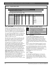
Address Switches
The switches on the D8128D OctoPOPIT set point
assignments and line termination. These switches are
easier to set before mounting the D8128D in the
enclosure.
Switches 1, 2, 3, and 4 assign the OctoPOPIT sensor
loops to point numbers on the control panel. Table 15
on page 42 shows the OctoPOPIT switch settings for
point assignments.
Switch 5 sets line termination. Refer to Table 16 on
page 42.