


D9412GV2/D7412GV2 | Operation and Installation Guide | 10.0 Off-Board Relays
50 Bosch Security Systems, Inc. | 5/05 | F01U003641B
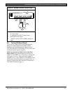
To install OctoRelays in the enclosure with the control
panel:
1. Align the module with one of the mounting
locations in the enclosure (refer to Figure 2 on
page 9).
2. Using the screws provided with the module, secure
the module in the enclosure.
Use the D137 Mounting Bracket or D9002
Mounting Skirt to install OctoRelays in enclosures
with no available module mounting locations.
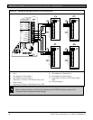
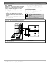
10.1.4 Wiring Connections
Power down the control panel to connect OctoRelays.
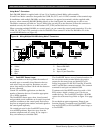
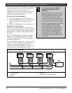
Refer to Figure 20 on page 48 and Figure 21 on page 49.
OctoRelays for Relays 1 to 64 connect to
Zonex 1, Terminal 28.
OctoRelays for Relays 65 to 128 connect
to Zonex 2, Terminal 26 on the D9412GV2
only.
Only one OctoRelay is shown wired to each Zonex bus
in Figure 20 on page 48and Figure 21 on page 49. Wire
additional OctoRelays in parallel. Review Section 6.0
Power Outputs on page 25 for information about
providing enough power for the relays.
The number of D8129 OctoRelays that can be
connected to each Zonex terminal on the D9412GV2
control panels is limited by the number of D8128D
OctoPOPITs connected.
Using D8129 OctoRelays and D8128D
OctoPOPITs together on the same Zonex
terminals is limited and depends on the
number of D8128 OctoPOPITs and D8129
OctoRelays connected to a single Zonex
Bus.
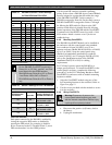
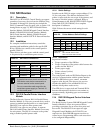
Refer to Table 19 for information about the
maximum number of D8128Ds and
D8129s you can connect to a single Zonex
bus.
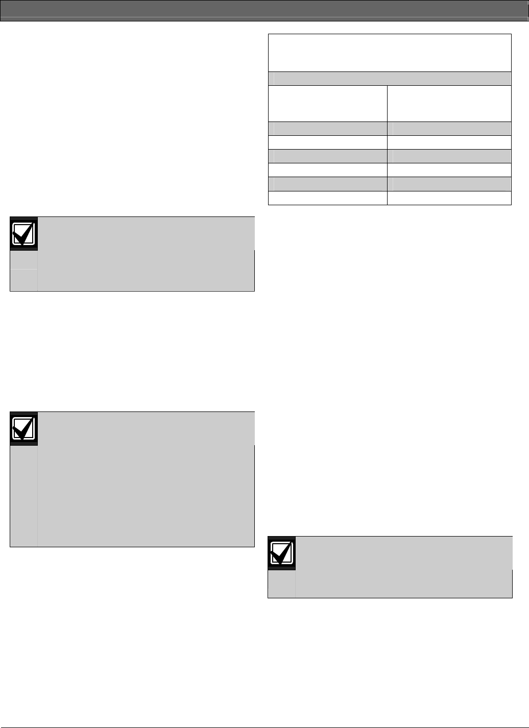
Table 19: Number of D8128Ds Used with
D8129s
If the number of
D8128Ds connected to a
single Zonex bus is:
Do not connect more than
this number of D8129s:
9 6
10 5
11 4
12 3
13 1
14 1
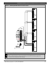
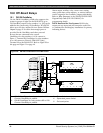
10.2 D811 Arm Status Relay Module
The D811 Arm Status Relay Module allows the
addition of a single off-board relay output to the
system. Alarm output, auxiliary relay, sensor reset,
arming status, point status, alarm memory, or remote
functions can be assigned to the D811 relay output. It is
not restricted to the Arming Status Mode only.
Relay Numbers for D811 Not Programmable: If the
D811 is connected to Zonex 1, Terminal 28, use relay
number 53 for the relay output. If the D811 is
connected to Zonex 2, Terminal 26 on the D9412GV2,
use relay number 117 for the relay output.
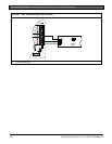
D811 Modules connect as shown in
Figure 22
on page
51and Figure 23 on page 52. Review Section 6.0 Power
Outputs on page 25 to ensure that enough power is
provided for the powered devices that connect to the
system. Refer to Relay Parameters in the
D9412GV2/D7412GV2 Program Entry Guide
(P/N: F01U003636) for programming details.
D811 Restricted for Fire Systems: The D811 relay
output is not supervised and cannot be used in fire or
combined fire and burglary installations for primary
indication devices.
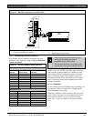
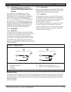
10.2.1 Relay Output
Relay outputs can activate when you are
programming the control panel.
Disconnect equipment connected to relay
outputs when you perform this function.
Each D811 relay output provides a Form C dry contact
rated for 1.0 A at 12 VDC. Normally-open, common,
and normally-closed terminals are available. When an
individual output is activated, continuity exists between
the normally-open and common terminals. When the
output is not activated, continuity exists between the
normally-closed and common terminals.