


D9412GV2/D7412GV2 | Operation and Installation Guide | 8.0 On-Board Points
.
Bosch Security Systems, Inc. | 5/05 | F01U003641B 31
8.0 On-Board Points
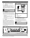
8.1 Terminals 11 to 22 Description
The control panel provides eight on-board points. Each
point functions independently and does not interfere
with the operation of the others. The control panel
monitors the sensor loops for normal, shorted, or open
conditions between an input terminal (11, 13, 14, 16,
17, 19, 20, or 22) and any of the point common
terminals (12, 15, 18, and 21). Programming for the
point determines how the control panel responds to
those conditions. Refer to the D9412GV2/D7412GV2
Program Entry Guide (P/N: F01U003636) for point
programming options. The control panel also monitors
the sensor loops for ground fault conditions if S4 is
latched (ground fault detect enabled).
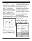
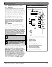
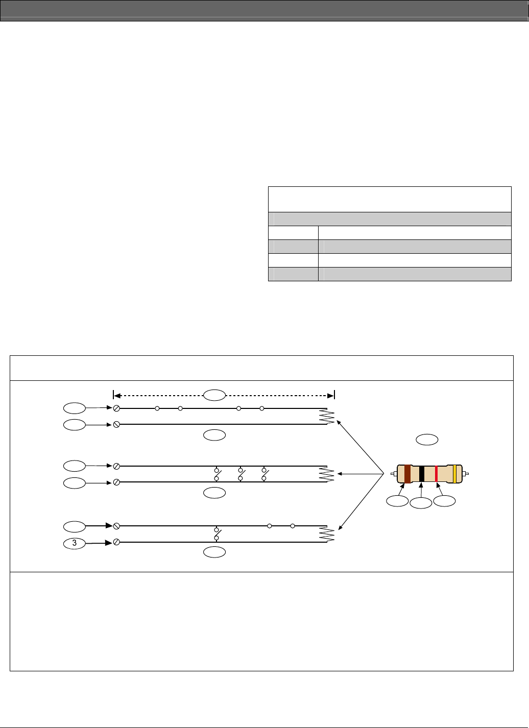
8.2 Point Sensor Loops
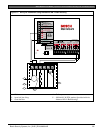
When wiring the on-board points (Figure 10), install
a 1 kΩ resistor at the far end of the sensor loop to
provide a reference for supervision. Dry-contact
sensing devices can be connected in series (normally-
closed) or in parallel (normally-open) to any of these
loops.
The number of normally-open and normally-closed
detection devices each sensor loop can supervise is
limited only by the resistance on the loop. The total
resistance for the wire length and contacts, minus the
end-of-line (EOL) resistor, must not exceed 100 Ω.
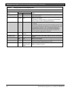
8.3 Point Parameters
The condition of on-board Points 1 to 8 is determined
by measuring the voltage across the point input
terminal and one of the common terminals. The sensor
loops must be connected and the 1 kΩ EOL resistor in
place.
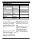
Table 10: Point Parameters
Loop Voltage Range
Open Greater than 3.7 VDC, but less than 5.0 VDC.
Normal Greater than 2.0 VDC, but less than 3.0 VDC.
Shorted Greater than 0.0 VDC, but less than 1.3 VDC.
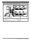
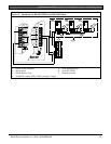
Figure 10: On-board Point Sensor Loop Wiring
1 k
Ω
4
5
6
9
7
10
1
2
3
2
3
2
8
9
10
1 - 100
Ω
maximum
2 - Point input terminal
3 - Common
4 - Normally-closed contacts (NC)
5 - Normally-open contacts (NO)
6- Combination: Normally-open contacts and
normally-closed contacts (NO/NC)
7 - P105F (Package of 8 EOL resistors) or
P105BL (Package of 8 UL Listed EOL
resistors) (P/N: 15093130-004)
8 - Brown
9 - Black
10 - Red