


D9412GV2/D7412GV2 | Operation and Installation Guide | 4.0 Installation
16 Bosch Security Systems, Inc. | 5/05 | F01U003641B
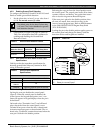
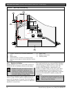
4.4 Installing the Control Panel
1. Place the control panel over the inside back of the
enclosure, aligning the large rectangular openings
of the mounting skirt with the mounting hooks of
the enclosure. Slide the control panel down so that
it hangs on the hooks. Refer to Figure 2, Item 2 on
page 15.
2. Remove the tape from the #6 x 1/4-in. screw in
the mounting tab on the control panel. The screw
passes through the mounting tab and into the skirt
mounting hole in the enclosure. Tighten the screw
to secure the control panel in the enclosure.
3. Connect earth ground to the control panel before
making any other connections. Refer to Section 4.5
Connecting Earth Ground.
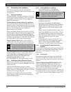
4.5 Connecting Earth Ground
4.5.1 Terminal 10
To help prevent damage from electrostatic charges or
other transient electrical surges, connect the system to
earth ground at Terminal 10 before making other
connections. Recommended earth ground references
are a grounding rod or a cold water pipe.
Warning:
Do not use telephone or electrical ground
for the earth ground connection. Use
1.8 mm (14 AWG) to 1.5 mm (16 AWG)
wire when making the connection.
Do not connect other control panel
terminals to earth ground.
4.5.2 Ground Fault Detect Enable
• A ground fault is a circuit impedance to earth
ground. The control panel has a ground fault
detection circuit that, when enabled, detects
ground faults on Terminals 1 to 9 and 11 to 32.
The control panel also detects and annunciates
ground faults on any device connected to it.
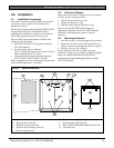
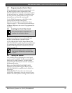
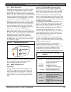
• To enable ground fault detection, the Ground Fault
Detect Enable jumper (S4) (Figure 3) must be
locked (closed) and a non-zero value must be
entered in the Area 5 Silent Alarm Relay. When
jumper S4 is in the unlocked (open) position, the
control panel does not detect ground fault
conditions.
• If a ground fault condition occurs, the keypads
display SERVC GND FAULT and the control panel
transmits a GROUND FAULT TROUBLE, AREA 1
(Modem IIIa
2
format only).
When the control panel recognizes that the ground
fault condition is corrected, and remains corrected
for between 5 to 45 consecutive seconds, a Restoral
Report is sent.
The D9412GV2 and D7412GV2 Control
Panels log and print a Ground Fault event
as a Trouble Point 256 if communicating in
Modem IIIa
2
format. If communicating in
BFSK format, the control panels generate
an Alarm Zone 5 event.
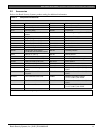
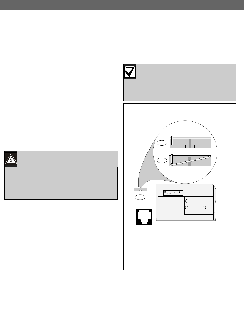
Figure 3: Ground Fault Detection
GROUND FAULT DETECT
Enabled
Disabled
S4
PHONE
LED
RED
ON when
communicating
OFF when idle
PHONE LINE SEIZED
TIP
RING
TELCO CORD
MODEL D161
3
1
2
1 - With S4 closed, control panel detects ground
faults.
2 - With S4 open, control panel does not detect
ground faults.
3 - S4, Ground fault detect enable.