


D9412GV2/D7412GV2 | Operation and Installation Guide | 9.0 Off-Board Points
46 Bosch Security Systems, Inc. | 5/05 | F01U003641B
Using Molex
®
Connectors
Each D8128D Module is supplied with a 30 cm (12 in.) female-to-female Molex cable assembly.
P1 and P2 are Molex connectors that parallel the COM, IN, OUT, and +12 VDC terminals on the terminal strip.
In installations with multiple D8128Ds, use these connectors (as opposed to terminals) with the supplied cable;
however, when connecting D8128D Modules directly to the control panel, the terminal strip is easier to use.
The Molex connectors provided are "keyed" (Molex plug can only fit in one direction). Ensure the connector is
attached correctly: the red wire is on the bottom of P1 (or P2) and the black wire is on the top.
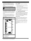
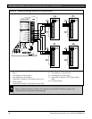
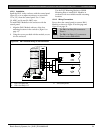
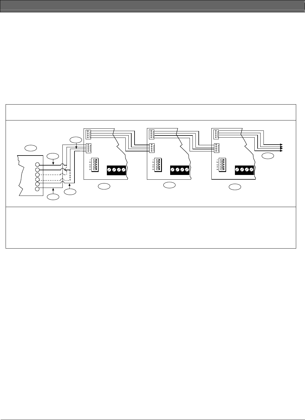
When connecting multiple D8128Ds to a control panel, you can connect the control panel terminals to P1 or the
COM, IN, OUT, and +12V terminals on the first D8128D. Then connect P2 of the first D8128D to P1 of the
second D8128D and so on (Figure 18).
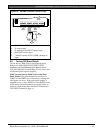
Figure 18: Wiring Multiple D8128Ds Using Molex
®
Connectors
COM IN OUT+12V
P1
P2
COM IN OUT+12V
P1
P2
28
27
26
25
24
23
COM IN OUT+12V
P1
P2
1
2
3
4
5
6
7
8
9
1 - D9412GV2 Control Panel
2 - Yellow
3 - Green
4 - Black
5- Red
6 - First D8128D
7 - Second D8128D
8 - Third 8128D
9- Up to 15 per Zonex Bus
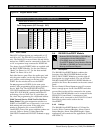
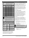
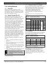
9.4.7 OctoPOPIT Sensor Loops
Only the resistance on the loop limits the number of
normally-open or normally-closed detection devices
each sensor loop can supervise. Resistance on each
sensor loop must be less than 100 Ω with the detection
devices connected.
Certain UL and NFPA applications can limit the
number of detection devices. Consult the appropriate
UL or NFPA standards.
The OctoPOPIT detects open, short, closed, normal,
and grounded circuit conditions on its sensor loops and
sends the conditions to the control panel. Each sensor
loop has an assigned point number and sends signals to
the control panel separately.
Use twisted-pair wire for the OctoPOPIT sensor loops
to avoid EMI problems. Run wires away from the
premises telephone and AC wiring. If you suspect a
noisy environment, use shielded cable.
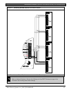
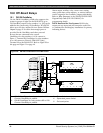
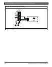
The OctoPOPIT has two rows of terminal numbers. In
the row nearest to the terminal blocks, the positive
outputs for the sensor loops are labeled P1 to P8.
Sensor loop outputs P1 and P2, P3 and P4, P5 and P6,
and P7 and P8 share common terminals. The common
terminals for each pair are labeled COM.
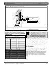
Terminate each OctoPOPIT sensor loop with a 1 kΩ
EOL resistor. Attach a resistor even if you do not
enable the loop. The OctoPOPIT includes a D105BL
resistor for each sensor loop. Refer to Figure 19 on page
47.
Do not duplicate point assignments. Points do not
function properly if assigned to an OctoPOPIT sensor
loop and a POPIT, to two OctoPOPIT sensor loops, or
to two POPITs.