


D9412GV2/D7412GV2 | Operation and Installation Guide | 1.0 Introduction
6 Bosch Security Systems, Inc. | 5/05 | F01U003641B
Figures
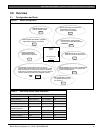
Figure 1: System Configuration .................................9
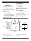
Figure 2: Enclosure Mounting..................................15
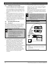
Figure 3: Ground Fault Detection............................16
Figure 4: Reset Pin.....................................................17
Figure 5: Non-Power-Limited Wiring .....................22
Figure 6: Charging and Battery LEDs.....................23
Figure 7: RJ31X Wiring............................................27
Figure 8: Phone Connector, Phone LED, and
Operation Monitor LED Locations.........27
Figure 9: D928 Dual Phone Line Switcher.............29
Figure 10: On-board Point Sensor Loop Wiring......31
Figure 11: Wiring for Installation Using the
Ademco AB-12 Bell/Housing..................33
Figure 12: Connecting the D8125 POPEX to the
D9412GV2 Control Panel........................36
Figure 13: Connecting the D8125 POPEX to the
D7412GV2 Panel ......................................37
Figure 14: Program Record Sheet..............................40
Figure 15: D8128D OctoPOPIT Layout...................41
Figure 16: Connecting D8128D OctoPOPITs
to the D9412GV2......................................44
Figure 17: Connecting D8128D OctoPOPITs
to the D7412GV2......................................45
Figure 18: Wiring Multiple D8128Ds Using
Molex
®
Connectors...................................46
Figure 19: D8128D OctoPOPIT Sensor Loops........47
Figure 20: D8129 Connections to the
D9412GV2.................................................48
Figure 21: D8129 Connections to the
D7412GV2.................................................49
Figure 22: D811 Module Wiring to the
D9412GV2.................................................51
Figure 23: D811 Module Wiring to the
D7412GV2.................................................52
Figure 24: Power at Keypads......................................54
Figure 25: Keyswitch Wiring......................................55
Figure 26: D9133 Jumper Setting for Address 80....58
Figure 27: DX4020i DIP Switch Settings..................59
Figure 28: DX4020 DIP Switch Settings...................60
Figure 29: D9133TTL-E Jumper Setting for
Address 88..................................................60
Figure 30: Reset Pin.....................................................61
Figure 31: Programmer and Accessory
Connections ...............................................61
Figure 32: D9412GV2 Faceplate ...............................62
Figure 33: D7412GV2.................................................63
Figure 34: D9412GV2, Power Supply Side..............64
Figure 35: D9412GV2, Input Points and
Peripheral Devices.................................... 65
Figure 36: D9412GV2, SDI Devices.........................66
Figure 37: D7412GV2, Power Supply Side.............. 67
Figure 38: D7412GV2, Input Points and
Peripheral Devices.................................... 68
Figure 39: D7412GV2, SDI Devices.........................69
Tables
Table 1: Related Documentation.............................. 7
Table 2: 9000GV2 Series Control Panel
Differences ................................................... 9
Table 3: Compatible Accessories ........................... 11
Table 4: Compatible Keypads ................................ 13
Table 5: Ground Fault Detection Status ................ 17
Table 6: Ground Fault Impedance Specifications 17
Table 7: Battery Discharge and Recharge
Schedule..................................................... 23
Table 8: Charging Status and Low Battery LEDs 24
Table 9: Phone Cord Lengths................................. 30
Table 10: Point Parameters .......................................31
Table 11: POPEX Modules....................................... 34
Table 12: Extra Point Events .................................... 34
Table 13: Off-Board Point Errors ............................. 35
Table 14: Data Expansion Loop Wire
Specifications ............................................. 38
Table 15: D8128D OctoPOPIT Switch Settings
for D9412GV2 and D7412GV2.............. 42
Table 16: Switch 5 Settings for Line Termination..42
Table 17: Terminal Strip Connections.....................43
Table 18: D8129 OctoRelay Switch Settings ..........49
Table 19: Number of D8128Ds Used with
D8129s........................................................ 50
Table 20: Keypad Address Settings..........................53
Table 21: Keypad Connections ................................ 53
Table 22: SDI Device Connections.......................... 57
Table 23: Printer Address Switch Settings............... 57
Table 24: Address Switch Settings for Access
Control Module.........................................58
Table 25: Zonex 1 Point Address Chart.................. 70
Table 26: Zonex 2 Point Address Chart.................. 71
Table 27: Specifications ............................................. 72