


D9412GV2/D7412GV2 | Operation and Installation Guide | 9.0 Off-Board Points
38 Bosch Security Systems, Inc. | 5/05 | F01U003641B
9.3 Installing the D8125 POPEX Module
For information on the Multiplex Bus
Interface, refer to the D8125 Multiplex Bus
Interface Operation and Installation Guide
(P/N: 36796).
Save the POPIT Label Sheets: The D8125 is
packaged with two sets of POPIT label sheets. One set
is marked “Bank 1” for use with the D7412GV2 and
D7212GV2. The other set is marked “Bank 2” for use
with the D9412GV2 and D9112. Use the sheets later to
label the POPITs. Refer to Section 9.3.6 POPIT Module
Point Assignments on page 40.
9.3.1 Mounting
To install the D8125 in the enclosure with the control
panel:
1. Align the D8125 POPEX Module with any of the
four mounting locations in the enclosure
(Figure 2 on page 15).
2. Using the screws provided with the module, secure
it in the enclosure.
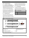
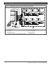
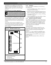
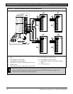
9.3.2 Wiring the D8125 to the Control Panel
To wire one or two D8125 Modules to the control
panel (Figure 12 on page 36 and Figure 13 on page 37):
Power Down the Control Panel: Disconnect the
positive (red) battery lead at the battery and unplug the
transformer.
For Points 9 to 127 (9 to 75 on D7412GV2):
1. Connect the GND terminal of the D8125 to
Terminal 23 on the D9412GV2 or to Terminal 9
on the D7412GV2.
2. Connect the OUT terminal of the D8125 POPEX
Module to ZONEX IN 1, Terminal 27.
3. Connect the IN terminal of the D8125 POPEX
Module to ZONEX OUT 1, Terminal 28.
4. Connect the AUX terminal of the D8125 to
Terminal 24 on the D9412GV2 or to Terminal 3
on the D7412GV2.
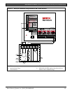
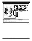
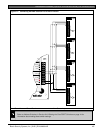
For Points 129 to 247 (D9412GV2 only):
1. Connect the GND terminal of the D8125 to
Terminal 23.
2. Connect the OUT terminal of the D8125 POPEX
Module to ZONEX IN 2, Terminal 25.
3. Connect the IN terminal of the D8125 POPEX
Module to ZONEX OUT 2, Terminal 26.
4. Connect the AUX terminal of the D8125 to
Terminal 24.
Refer to Section 9.3.4 Wiring Data Expansion Loops to
POPEX Modules on page 39 for instructions on
connecting POPITs to the D8125 POPEX Module.
9.3.3 Wiring POPITs to the Data Expansion Loop
Use one two-wire data expansion loop or distribute the
POPITs on up to three loops. Setting DIP switches on
the POPIT Modules assigns them to point numbers.
Refer to Section 9.3.6 POPIT Module Point Assignments on
page 39.
Review Section 4.6.2 Installing and Wiring Detection
Devices on page 18 to determine if shielded wire is
required. Determine the wire gauge for the length of
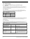
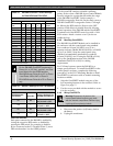
each data expansion loop using Table 14
T
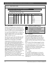
able 14: Data Expansion Loop Wire
Specifications
Maximum Length of All Data Expansion Loops
Combined
AWG Length in Meters (Feet)
22 548 (1800)
20 881 (2890)
18 1402 (4600)
16 2231 (7320)
14 3551 (11,650)
Combine Data Expansion Loops: The maximum
lengths shown in Table 14 are for all data expansion
loops connected to the same POPEX Module
combined.
Wiring POPITs Together: Do not connect POPITs to
each other in series or with a T-tap. Doing so might
cause random missing POPIT conditions.
To connect POPITs to one another in parallel:
1. Connect the positive (+) data terminal from one
POPIT to the positive (+) data terminal on the next
POPIT.
2. Connect the negative (-) data terminal from one
POPIT to the negative (-) data terminal on the next
POPIT.
3. Repeat Steps 1 and 2 to connect all POPITs to the
expansion loop. It is not necessary to wire the
POPITs in any particular order on the loop. The
switch setting on each POPIT assigns it a point
number, regardless of its physical location.
Before installing the POPITs, make sure the
resistance on the data expansion loop is no
more than 40 Ω.
Three-inch Clearance for Tampered POPITs:
Mount tampered POPIT modules at least 7.6 cm (3 in.)
apart to prevent the tamper magnets from interfering
with each other.