


D9412GV2/D7412GV2 | Operation and Installation Guide | 7.0 Telephone Connections
.
Bosch Security Systems, Inc. | 5/05 | F01U003641B 27
7.0 Telephone Connections
7.1 Registration
The Bosch Security Systems D9412GV2/D7412GV2
Control Panels are registered with the Federal
Communication Commission (FCC) under Part 68, for
connection to the public telephone system using an
RJ31X or RJ38X jack installed by the local telephone
company.
An RJ31X jack can be modified by placing a
jumper wire between Terminals 2 and 7 to
become an RJ38X jack.
7.2 Notification
Do not connect registered equipment to party lines or
coin-operated telephones. Notify the local telephone
company and provide the following information before
connecting the control panel to the telephone network:
• The particular line to which the control panel will
be connected
• Make (Bosch Security Systems), model
(D9412GV2 or D7412GV2), and serial number of
the control panel
• FCC registration number: AJ9MUL-46532-AL-E
• Ringer equivalence for the control panel: 0.4B
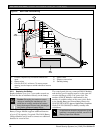
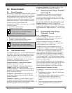
7.3 Location
To prevent jamming of signals, wire the RJ31X or
RJ38X jack before the in-house telephone system to
support line seizure (Figure 7). Install the jack on the
street side of the telephone switch, wired ahead of any
PBX equipment. Line seizure temporarily interrupts
normal telephone usage while the control panel sends
data. After installation, confirm that the control panel
seizes the line, acquires dial tone, reports correctly to
the receiver, and releases the telephone line to the in-
house telephone system.
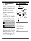
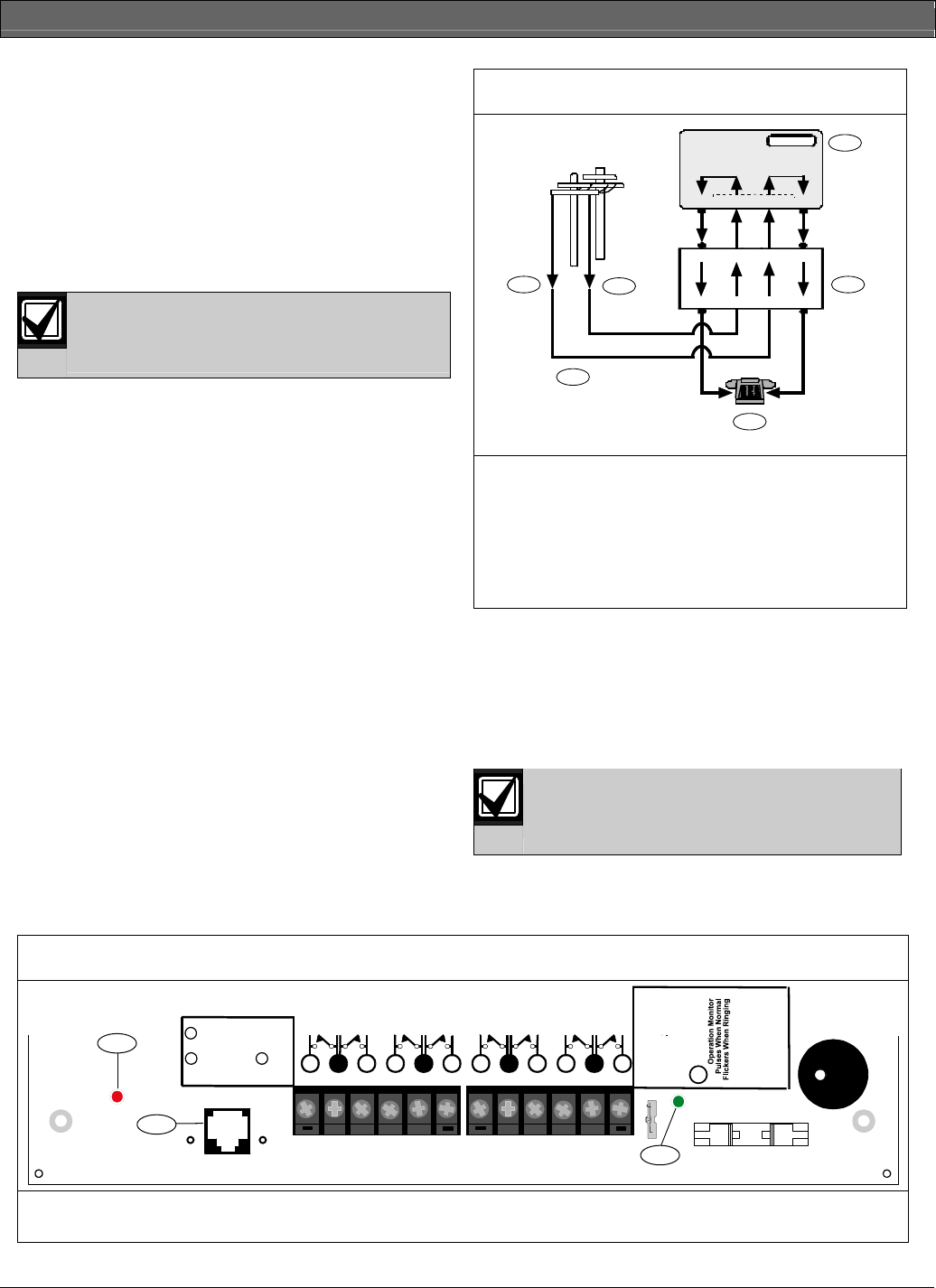
Figure 7: RJ31X Wiring
4
5
8
458
4
58
1
1
1
T1
T
R
R1
RING (red)
TIP (green)
RJ31X
2
7
1
2
3
4
5
6
1 - RJ31X Jack
2 - (TIP)
3 - (RING)
4 - Telco connector block
5 - Outside telco
6 - Premises telephone
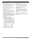
7.4 Telephone Cord Connection
Connect one end of a D161 (2.1 m [7 ft.]) or a D162
[61 cm (2 ft.)] Telephone Cord to the telco cord
connector located on the bottom left corner of the
control panel. Refer to Figure 8. Connect the other end
to the RJ31X or RJ38X jack.
To supervise the phone cord, use an RJ38X
jack.
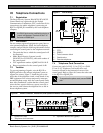
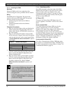
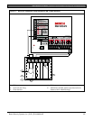
Figure 8: Phone Connector, Phone LED, and Operation Monitor LED Locations
1211 13 1514 16 1817 19 2120 22
PHONE
LED
RED
ON when
communicating
OFF when idle
PHONE LINE SEIZED
TIP
RING
TELCO
RING
TIP
PHONE LINE
SEIZED
1
2
3
GRN
Point 8
S3 Option
Closed = 1K
Ω
EOL
Normal Operation
Open =AB-12 UL
Bell Box 220 K
Ω
D5200/D5360
PROG CONN
TELCO CORD
MODEL D161
1 - Phone LED (red)
2 - Telephone cord connector
3 - Operation Monitor LED (green)