


D9412GV2/D7412GV2 | Operation and Installation Guide | 13.0 Programmer and Accessory Connections
.
Bosch Security Systems, Inc. | 5/05 | F01U003641B 61
13.0 Programmer and Accessory
Connections
13.1 Programmer Connector
Refer to the D5200 Operation Manual
(P/N: 74-06176-000) for complete information on using
the D5200 programmer.
To connect and disconnect the programmer:
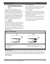
1. Lock the Reset Pin (Figure 30).
2. Connect the D5200 Data/Power cord to the
programming connector on the control panel
(Figure 31).
3. Perform the desired programming function (send
or receive program).
4. Disconnect the programmer.
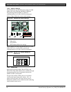
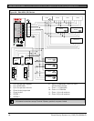
Figure 30: Reset Pin
Reset Pin
Disable All Except Battery
Charging And Programming
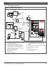
PERIPHERAL DEVICE CONNECTIONS
RED POWER +
YELLOW DATA BUS A
GREEN DATA BUS B
BLACK COMMON
32
31
30
29
1
2
1 - Reset Pin locked (closed)
2 - Reset Pin normal (open) for normal control
panel operation
13.2 Programmer Access Reports
When a program is sent to the control panel, the
control panel sends a Prog Access OK report 10
seconds after the handler exits or when the
programmer disconnects. The prompt in routing must
be programmed Yes to send this report.
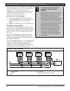
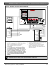
13.3 Accessory Connector
Use the accessory connector to connect the control
panel to the D928 Dual Phone Line Switcher. The
accessory connector is on the bottom right corner of
the I/O board (Figure 31). The D928 lets the control
panel use two telephone lines to send reports.
Refer to Section 7.11 D928 Dual Phone Line Switcher on
page 29 for installation and operating instructions.
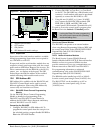
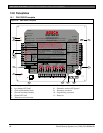
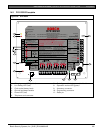
Figure 31: Programmer and Accessory
Connections
26
25
NEX IN 2
NEX POWER +
24
ONEX COMMON
23
GRN
D5200/D5360
PROG CONN
1
2
1 - Accessory connector
2 - Programming connector