


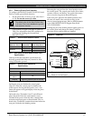
D9412GV2/D7412GV2 | Operation and Installation Guide | 6.0 Power Outputs
.
Bosch Security Systems, Inc. | 5/05 | F01U003641B 25
6.0 Power Outputs
6.1 Circuit Protection
Three Positive Temperature Coefficients (PTCs) protect
the control panel from short circuits on the continuous
and programmable power outputs. If the control panel
is programmed for power supervision and a short
circuit occurs on one of the power outputs, the control
panel sends a BATTERY LOW or BATTERY MISSING
for Bosch Security Systems Modem IIIa
2
Communication Format, or TROUBLE ZN 9 for BFSK.
One PTC protects :
• Terminal 3: Auxiliary Power
• Terminal 24: Zonex Power.
A short-circuit on one terminal disrupts
power to the other terminal.
Another PTC protects:
• Terminal 6: Alarm Power Output
• Terminal 7: Alternate Alarm Power Output
• Terminal 8: Switched Auxiliary Power.
A short-circuit on one of the terminals
disrupts power to the other two terminals.
The third PTC protects Terminal 32: Power +.
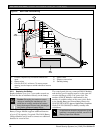
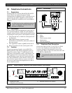
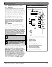
6.2 Total Available Power
The system produces up to 1.4 A of combined power at
10.2 VDC to 13.9 VDC for all powered devices. The
outputs listed below share the available power. These
outputs are shown as red circles on the faceplate.
Terminal 3 - Auxiliary Power: Use this terminal to
power devices requiring continuous power.
Terminal 6 (Relay A) - Alarm Power Output:
Normally open, power on alarm.
Terminal 7 (Relay B) - Alternate Alarm Power
Output: Normally open, power on alarm.
Terminal 8 (Relay C) - Switched Auxiliary Power:
Normally closed, switches power off when the Sensor
Reset command is executed.
Terminal 24 - Zonex Power: Use this terminal to
power Zonex modules such as the D8125, D8128D,
and D8129 Modules.
Terminal 32 - Power +: Use this terminal to power
serial device interface (SDI) devices such as keypads,
the D9131A Parallel Printer Interface Module, and the
D9210B Wiegand Control Interface Module.
Accessory Connector: The D928 Dual Phone Line
Switcher connects to the accessory connector.
6.3 Continuous Power Output Terminals
3, 8, 24, and 32
The continuous current draw for powered devices
connected to Terminals 3, 8, 24, and 32, and the
accessory connector must not exceed 1.4 A. Devices
powered from these outputs must operate over a range
of 10.2 VDC to 13.9 VDC.
Power Restricted for Fire and Combined Fire and
Burglary Systems: Use the Fire System Power
Formula to calculate the current available for fire and
combined fire and burglary systems (refer to Section 6.4
Programmable Power Output Terminals 6, 7, and 8 on page
25).
6.4 Programmable Power Output
Terminals 6, 7, and 8
6.4.1 Programming
The power outputs at Terminals 6, 7, and 8 are
programmed as Relays A, B, and C. All relays are
programmed in the Relays section.
Relays are assigned a relay type, (Fire Bell, for
example) when they are assigned to an area. Relays
can be assigned to one or more areas.
The Bosch Security Systems defaults set Relay A
(Terminal 6) as a Steady Alarm Bell output, Relay B
(Terminal 7) as a Pulsed Fire Bell output, and Relay C
(Terminal 8) as a Verification or Reset output for
smoke detectors. The D9412GV2/D7412GV2 Program
Entry Guide (P/N: F01U003636) contains complete
instructions for programming relays. Refer to Sections
6.4.2 Terminals 6 and 7, 6.4.3 Fire System Power Formula,
and 6.4.4 Terminal 8 on page 26 for descriptions of the
functions of each terminal.
Refer to the Bell Parameters section of the program to
set the Fire Bell, Alarm Bell output responses for relays.
Four annunciation patterns are available: Steady,
Pulsed, California Standard, and Temporal Code 3.
Voltage Output at Terminals 6, 7, and 8
If Terminals 6, 7, and 8 do not provide the expected
output, check:
• Programming for Relays A, B, and C in the relays
section of the program.
• Bell Parameters section of the program to confirm
that the Alarm and Fire Bell responses are
programmed for the expected duration and
pattern.
• Point Assignments section to confirm that each
point is programmed for the expected local
response.