


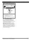
D9412GV2/D7412GV2 | Operation and Installation Guide | 10.0 Off-Board Relays
.
Bosch Security Systems, Inc. | 5/05 | F01U003641B 51
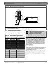
10.2.2 Installation
Install the D811 in the enclosure with the control panel
(Figure 22) or in an adjacent enclosure no more than
1.5 m (5 ft.) from the control panel. Use 1.5 mm
(16 AWG) to 0.8 mm (22 AWG) wire.
To install D811 Modules in the enclosure with the
control panel:
1. Align the D811 Module with any of the four
mounting locations in the enclosure (Figure 2 on
page 15).
2. Using the screws provided with the module, secure
it in the enclosure.
Use the D137 Mounting Bracket or D9002
Mounting Skirt to install D811 Modules in
enclosures with no available module mounting
locations.
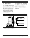
10.2.3 Wiring Connections
Power down the control panel to connect D811
Modules as shown in Figure 22 on this page and
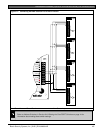
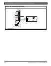
Figure 23 on page 52.
The D811 for Relay 53 connects to
Zonex 1.
The D811 for Relay 117 connects to
Zonex 2 on the D9412GV2.
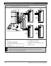
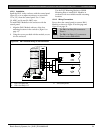
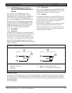
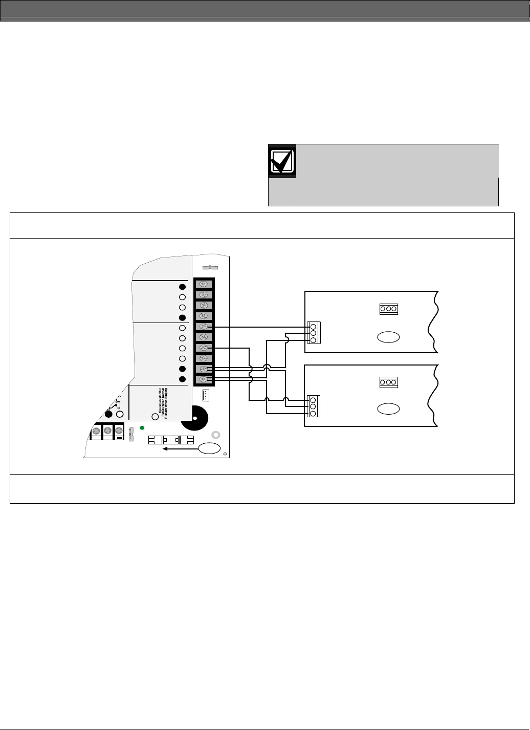
Figure 22: D811 Module Wiring to the D9412GV2
Reset Pin
Disable All Except Battery
Charging And Programming
PERIPHERAL DEVICE CONNECTIONS
RED POWER +
YELLOW DATA BUS A
GREEN DATA BUS B
BLACK COMMON
ZONEX OUT 1
ZONEX IN 1
N.F.P.A.
Style 3.5
Signaling
Line
Circuits
32
31
30
29
28
27
ZONEX OUT 2
26
25
ZONEX IN 2
ZONEX POWER +
24
ZONEX COMMON
23
21 22
5
GND
AUX
DATA
5
GND
AUX
DATA
3
2
1
GRN
D5200/D5360
PROG CONN
Point 8
S3 Option
Closed = 1K
Ω
EOL
Normal Operation
Open =AB-12 UL
Bell Box 220 K
Ω
1 - D811 for Relay 53
2- D811 for Relay 117
3- On-board points