


D9412GV2/D7412GV2 | Operation and Installation Guide | 12.0 SDI Devices
.
Bosch Security Systems, Inc. | 5/05 | F01U003641B 59
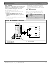
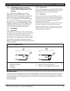
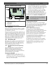
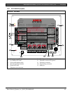
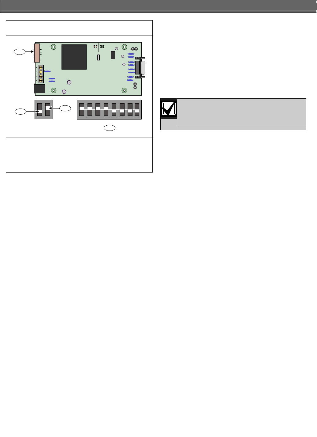
Figure 27: DX4020i DIP Switch Settings
SER
RxTx
BUS
Rx Tx
LED
ENABLE
DB9 GND
ENABLE
P1
P6
P2
P3
1 2 4 8 16 32 64 128
ON
123456
78
1 2 4 8 16 32 64 128
ON
123456
78
1
2
3
4
1 - Address DIP switches
2 - OFF position
3 - ON position
4 - SDI Address 80 switch settings
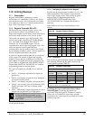
12.5.3 Supervision
Supervision of the serial interface module is available
through programming. Supervision is not required to
use a DX4010i or a D9133.
If supervised, and the serial interface module does not
respond to control panel supervision polls, the control
panel sends an SDI Failure Report to the receiver. If it
fails to communicate with the DX4010i or the D9133,
SERVC SDI 80 displays at the keypad. The SDI
Failure Report includes the address of the troubled
module indicating which module needs service.
12.6 SDI Address 88
SDI Address 88 is available with the D9412GV2 and
D7412GV2 Control Panels and is used for several
different applications. When using SDI Address 88,
connect only one listed device at a time.
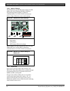
12.6.1 D9133DC Direct Connect Programming
Module
Use the D9133DC Direct Connect Programming
Module to handle local programming of the
D9412GV2 and D7412GV2 Control Panels. In
addition, the D9133DC allows diagnostic and history
retrieval. D9133DC is not UL Listed.
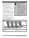
Connecting the D9133DC
1. Configure D9133DC for SDI Address 88. To
program the control panel when the reset pin is in
the unlocked position, program Enable SDI RPS to
Yes in the GV2AUX handler.
2. Connect D9133DC to Com Port 1 or Com Port 2
on the PC. The D9133DC has a DB-9 female serial
connector. A null-modem cable must be purchased
separately to connect the D9133DC to a PC.
3. Using 0.8 mm (22 AWG) or 1.2 mm (18 AWG)
wire, connect the D9133DC SDI terminals (SDI
PWR, SDI A, SDI B, and SDI COM) to the
control panel’s SDI terminals (Terminals 29 to 32).
To send or receive the control panel’s program, place
the Reset Pin in the Locked or Unlocked position.
Locking the Reset Pin when programming
the control panel improves the uploading
and downloading times.
Used as an External Modem
The D9133DC can operate as an external modem
when using Remote Programming Software (RPS) with
the control panel. Refer to the D9412GV2/D7412GV2
Program Entry Guide (P/N: F01U003636) for
programming details.
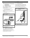
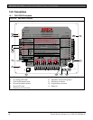
12.6.2 Network Interface Modules
The Bosch Security Systems DX4020 Network
Interface Module and D9133TTL-E Network Interface
Module are four-wire powered SDI devices that
provide connection for two-way communication over
Ethernet networks to D9412GV2 and D7412GV2.
For programming information on enhanced
communications, refer to the D9412GV2/D7412GV2
Program Entry Guide (P/N: F01U003636).
The DX4020 can be installed up to 305 m (1000 ft)
from the control panel using 0.8 mm (22 AWG) wire.
The D9133TTL-E can be installed up to 305 m
(1000 ft) from the control panel using 1.2 mm
(18 AWG) wire.