47
3
JOHNSON CONTROLS
FORM 100.50-NOM6 (1207)
SECTION 3 – START-UP
To protect warranty, this equip ment
must be in stalled and ser viced by an
authorized JOHNSON CONTROLS
ser vice me chan ic or a qualifi ed service
per son ex pe ri enced in air han dling
and con dens er unit in stal la tion.
Installation must com ply with all ap-
pli ca ble codes, par tic u lar ly in regard
to elec tri cal wiring and oth er safety
elements such as re lief valves, HP
cut-out settings, design work ing pres-
sures and ven ti la tion re quire ments
con sis tent with the amount and type
of re frig er ant charge.
Lethal voltages exist within the Con-
trol Panel. Before servicing, open and
tag all disconnect switches.
Reference publication Form 100.50-
SU1 (507) “Quick Startup Guide” for
additional information.
CRANKCASE HEATERS
With power applied to the rooftop unit, the crank case
heater for each com pres sor will be ON when ev er the
com pres sor is not running. The heater is in ter locked into
the compressor motor contactor and is not con trolled
by the mi cro pro ces sor.
The purpose of the crankcase heater is to pre vent
the migration of refrigerant to the crank case during
shut down, assuring proper lu bri ca tion of the com pres sor
on start-up.
Anytime power is removed from the unit for more than
an hour, the crankcase heater should be left on for 24
hours prior to start.
Power must be applied to the rooftop
unit 24 hours prior to starting the unit
com pres sors. Failure to observe this
re quire ment can lead to com pres sor
dam age and void ing of the com pres sor
war ran ty.
CHECKING THE SYS TEM PRIOR TO INI TIAL START
(NO POWER)
Unit Checks
1. Inspect the unit for shipping or installation dam-
age.
2. Visually check for refrigerant piping leaks.
3. The compressor oil level should be main tained so
that an oil level is visible in the sight glass. The
oil level can only be tested when the com pres sor is
run ning in stabilized conditions, guar an tee ing that
there is no liquid refrigerant in the lower shell of the
com pres sor. In this case, the oil must be between
1/4 and 3/4 in the sight glass. At shutdown, the oil
level can fall to the bottom limit of the oil sight
glass.
4. Check the control panel to assure it is free of for-
eign material (wires, metal chips, etc.).
5. Visually inspect fi eld wiring (power and control).
Wir ing MUST meet N.E.C. and local codes.
6. Check tightness of terminal lugs inside the pow er
pan el on both sides of the contactors, over loads,
fus es, and pow er con nec tions.
7. Verify fuse sizing in main cir cuits.
8. Verify fi eld wiring for ther mo stat (if ap pli ca ble),
op tion al zone sen sor, etc.
9. Verify all applicable pneumatic tubing has been
fi eld in stalled for Duct Static Pressure Transducers
(VAV units), op tion al building pressure transducer
for power exhaust option, and outdoor static pres-
sure prove.
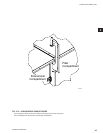
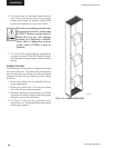
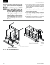
10. Supply exhaust and return fan isolators spring bolts
are removed (refer to Fig ure 3-1).
11. Verify proper bearing and locking collar torque
val ues on supply and exhaust fans (refer to Main-
te nance section of manual).
12. Verify proper drive alignment of supply and ex-
haust fans (refer to Maintenance section of man-
u al).


