35
2
JOHNSON CONTROLS
FORM 100.50-NOM6 (1207)
VAV Heat Relay Output
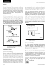
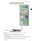
This is a 24 VDC output that is turned on when the
unit is in the heating mode. The fi eld can use this as
a signal to trigger the opening of the VAV boxes for
heating operation. This feature uses two ¼ inch male
tabs identifi ed as (VAV OPEN +) and (VAV OPEN -)
on the Simplicity control board.
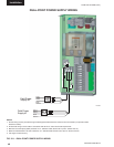
Supply Air Temperature Reset
An external 0 to 10 VDC input can be applied to
terminals (REM+) and (REM-) at terminal block P19
on the Simplicity control board to reset the supply air
temperature set point for VAV operation. The units
follows interprets the voltage input as follows:
Below 1.0 VDC – the blower is de-energized
Below 1.5 VDC – the cooling and heating is
disabled
At 2.0 VDC – the control uses the lower set
point
Between 2.0 VDC and 10 VDC the change in set
point is proportional to the change in voltage.
At 10.0 VDC – the control uses the upper set
point
COMMUNICATION
The Simplicity Unit Controller is designed to
communicate using Modbus Client protocol. Through
the use of a ModLINC translator the unit can also
communicate using BACnet MS/TP protocol.
Through the use of a FREEnet Serial or USB adapter
the Simplicity Unit Controller can be connected directly
to a computer. Multiple units can be daisy chained
together and through the use of the adapter connected to
a computer or a network. This allows remote monitoring
of the unit as well as the ability to change settings and
options from a remote location.
Connection to the unit is done through either of two
RS-485 connections. The P4 terminal block has screw
connections with terminal A being the – and terminal
B being the +. The P5 connecter is designed to allow
the mating connector from the FREEnet Serial or USB
adapter to be plugged in.
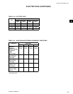
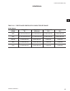
See Table 6-1 for parameter points list.
DIRTY FILTER SWITCH
On units with a dirty fi lter switch option, an adjustable
differential pressure switch is installed to monitor the
pressure drop across the fi lters. When the pressure
drop across the fi lters exceeds the setting of the switch,
the switch closes sending a 24-volt signal to the Unit
Controller. The Unit Controller posts a warning in
the service memory buffer; but will not shut down the
unit.


