37
2
JOHNSON CONTROLS
FORM 100.50-NOM6 (1207)
POWER WIRING
Field wiring to the unit must conform to provisions
of National Electrical Code (NEC) ANSI / NFPA 70-
Lat est Edition and / or local ordinances. The unit must
be electrically grounded in accordance with the NEC
and / or local codes. Voltage tolerances, which must be
main tained during starting and running con di tions, are
in di cat ed on the unit data plate.
The internal wiring harnesses furnished with this unit
are an integral part of the design certifi ed unit. Field
al ter ation to comply with electrical codes should not
be required. If any of the wire supplied with the unit
must be replaced, replacement wire must be of the type
shown on the wiring diagram and the same minimum
gauge as the replaced wire.
Power supply to the unit must be NEC Class 1 and must
comply with all applicable codes. A disconnect switch
must be provided (factory option available). The switch
must be separate from all other cir cuits. Wire entry at
knockout openings re quires conduit fi ttings to comply
with NEC and/or Local Codes.
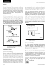
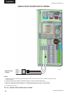
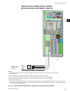
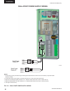
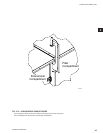
Refer to Figures 2-9, 2-10 & 2-11 for typical fi eld wiring
and to the appropriate unit wiring diagram mounted in side
control doors for control circuit and power wiring
information.
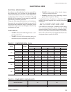
ELECTRICAL SERVICE SIZING
Electrical service re quired for the cool ing only eco
2
roof top, use the ap pro pri ate cal cu la tions listed below
from U.L. 1995. Based on the op er at ing mode and
con fig u ra tion of the roof top, the cal cu la tions will
yield dif fer ent MCA (minimum cir cuit am pac i ty), and
MOP (max i mum overcurrent protection). MCA and
Overcurrent Pro tec tion De vice Data is supplied on
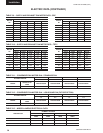
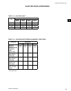
the unit data plate. Also refer to Table 2-7, 2-9, 2-10,
2-11, 2-12, 2-13 and 2-14, Electrical Data.
The following calculations apply to electrical data for
the rooftop unit. All con cur rent load con di tions must
be con sid ered in the cal cu la tions, and you must use the
highest value for any com bi na tion of loads.
Minimum Circuit Ampacity (MCA) is based on 125%
of the rated load amps for the largest mo tor plus 100%
of the rated load amps for all other loads in clud ed in the
circuit, per N.E.C. Article 440-34.
The minimum rec om mend ed disconnect switch is based
on 115% of the rated load amps for all loads in clud ed
in the circuit, per N.E.C.
Maximum overcurrent protection is based upon 225%
of the rated load amps for the largest motor plus 100%
of the rat ed load amps for all other loads in clud ed in
the cir cuit, per N.E.C. Article 440-22. If the max i mum
overcurrent pro tec tion does not equal a stan dard cur rent
rating of an overcurrent protective device, then the
marked max i mum rating is to be the next lower stan dard
rating. How ev er, if the de vice se lect ed for maximum
overcurrent protection is less than the MCA, then se lect
the lowest standard max i mum fuse size great er than or
equal to the MCA.
Figures 2-9, 2-10 & 2-11 show the power wiring that
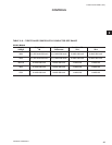
must be fi eld sup plied and installed. See Table 2-16 for
the allowable conductor wire size for the electrical lugs
in the unit.
For dual point power connections, TB1 in the pow er
panel supplies the all unit com pres sors and con dens er
fans. TB2 in the power panel sup plies pow er to the unit
supply, return and exhaust fans, and control cir cuit ry.
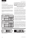
All wiring must conform to the Na-
tion al Elec tri cal Code (NEC) and
lo cal codes that may be in ad di tion to
NEC.
POWER WIRING


