165
JOHNSON CONTROLS
FORM 100.50-NOM6 (1207)
8
Supply Air Temperature Sensor Alarm (20)
This alarm indicates the supply air temperature input is
either open or shorted. The display will show a value
of –40.0° F. The supply air temperature input is at
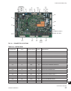
SAT+ and SAT- of the P11 connector. To trouble shoot
compare the resistance of the input to the actual supply
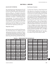
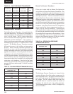
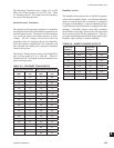
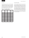
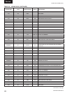
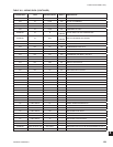
air temperature using Table 8-1.
Return Air Temperature Sensor Alarm (21)
This alarm indicates the return air temperature input is
either open or shorted. The display will show a value
of –40.0° F. The return air temperature input is at
RAT+ and RAT- of the P11 connector. To trouble shoot
compare the resistance of the input to the actual return
air temperature using Table 8-1.
Outdoor Air Temperature Sensor Alarm (22)
This alarm indicates the outdoor air temperature input
is either open or shorted. The display will show a
value of –40.0° F. The outdoor air temperature input
is at OAT+ and OAT- of the P11 connector. To trouble
shoot compare the resistance of the input to the actual
outdoor air temperature using Table 8-1.
Dirty Filter Switch Alarm (23)
This alarm will have no effect on the operation of the
unit. The alarm indicates the dirty fi lter switch contacts
have closed indicating the pressure drop across the fi lters
is above the setting of the switch. The 24 VAC output
to the switch is at terminal FILT wire 391 of the P22
connector and the input to the control is at terminal FILT
wire 390 of the P22 connector.
Supply Fan Air Proving Switch (24)
This alarm indicates there was a call for supply fan
operation and after 90 seconds of supply fan operation
the switch did not close. The Unit Controller will retry
the fan output every 30 minutes for three retires. If after
the three retries the Unit Controller will lockout heating
and cooling operation.
On a VAV unit the Unit Controller will also use the duct
static pressure input to qualify supply fan operation.
If the Unit Controller reads more then 0.05" WC it
will continue to identify the alarm but allow the unit
to operate.
The 24 VAC output to the switch is at terminal APS wire
412 of the P11 connector and the input to the control is
at terminal APS wire 411 of the P11 connector.
Supply Fan Air Proving Switch Closed Alarm (25)
This alarm indicates the call for supply fan operation
has been terminated and after 90 seconds of supply fan
operation the switch remained closed. The control will
fl ash the alarm but allow the unit to operate normally.
The 24 VAC output to the switch is at terminal APS wire
412 of the P11 connector and the input to the control is
at terminal APS wire 411 of the P11 connector.
Microelectronics Failure Alarm (26)
This alarm indicates a problem with the Unit Controller
microelectronics has occurred and the Unit Controller
is operating on default values. Try recycling power
to the control. If the fault reappears replace the Unit
Controller.
Microelectronics Failure Alarm (27)
This alarm indicates a problem with the Unit Controller
microelectronics has occurred and the Unit Controller is
shut down. Try recycling power to the control. If the
fault reappears replace the Unit Controller.
Supply Fan Overload Alarm (28)
The Unit Controller monitors this circuit anytime
the supply fan is operative. If this input is lost for
50 milliseconds, the control will shut down all unit
operation. If the voltage input does not return in 5-
minutes the control will turn on the alarm.
If the voltage returns the Unit Controller will log the
fi rst incident and track the run time. If the switch opens
three times in a two-hour period the Unit Controller will
shut down the unit.
The 24 VAC output to the switch is at terminal FOVR
wire 404 of the P16 connector and the input to the control
is at terminal FOVR wire 403 of the P16 connector.


