44
JOHNSON CONTROLS
FORM 100.50-NOM6 (1207)
Installation
DUCT SYSTEM
Duct Connection Guidelines
All intake and discharge air duct connection to the
unit may be made directly to the unit. These air duct
con nec tions should be on fl exible material and should
be installed so they are suffi ciently loose. Duct runs
and transitions must be made carefully to hold friction
loss to a min i mum. Avoid short turns, and duct elbows
should con tain splitters or turning vanes.
Duct work connected to the fan discharge should run in a
straight line for at least two equiv a lent outlet di am e ters.
Never dead head the dis charge into the fl at sur face of
a plenum.
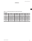
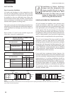
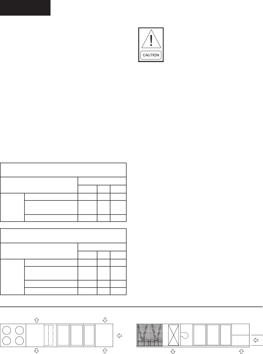
Refer to Table 2-17 and 2-18 for available supply and
return duct connection confi guration.
TABLE 2-17 – SUPPLY AIR DUCT CONNECTION
CONFIGURATIONS
UNIT CONFIGURATION
SUPPLY AIR
BOTTOM LEFT RIGHT
50-61 TONS
COOLING ONLY
√
√√
COOL/GAS HEAT 375-750
MBH
√√N/A
COOL/GAS HEAT 1125 MBH √ N/A N/A
TABLE 2-18 – RETURN AIR DUCT CONNECTION
CONFIGURATIONS
UNIT CONFIGURATION
SUPPLY AIR
BOTTOM LEFT RIGHT
50-61 TONS
NO EXHAUST √ √ √
BAROMETRIC RELIEF
DAMPER
√√N/A
POWERED EXHAUST FAN √ √ N/A
RETURN FAN √ N/A N/A
Installation of elbows, discharge
damp er and oth er abrupt fl ow area
changes installed di rect ly at the fan
outlet will cause system losses. These
losses must be taken into account
dur ing the de sign phase and must be
add ed to any fi eld mea sure ments.
SOUND AND VIBRATION TRANS MIS SION
All roof mounted air handling units generate some
sound and vibration, which may or may not require
some special treatment of the air con di tioned space. The
noise gen er at ed by the air handling unit is dependent
on the speed of the fan, the amount of air the fan is
moving, the fan type and the static effi ciency of the fan.
In ap pli ca tions where sound and vibration transmissions
may be ob jec tion able, good acoustical engineering
prac tic es must be incorporated in the system design.
The eco
2
unit is designed for lower sound levels than
competitive units by using fl exible fan connections,
fan spring isolators, double-wall construction, multiple
fan options, and lower speed and horsepower fans. For
VAV applications, VFDs are used instead of inlet guide
vanes. Additional sound attenuation can be obtained
using compressor sound blankets and fi eld-supplied
sound attenuators when necessary.
Even with these equipment design features, the
acoustical characteristics of the entire installation must
never be overlooked. Additional steps for the acoustical
characteristics of a rooftop installation should be
addressed during the design phase of a project to avoid
costly alterations after the installation of the equipment.
During the design phase of a project, the designing
engineer should consider, at a minimum, the impact of
the equipment location, rooftop installation, building
structure, and duct work.
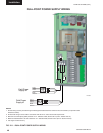
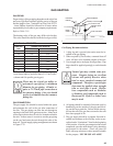
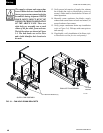
BOTTOM
FRONT
LEFT
RIGHT
FRONT
Discharge Return
LD08045
NOTE:
This diagram is provided as a visual reference of the eco
2
discharge & return air openings & locations for all sizes. Please refer to Fig 2-4 for exact
size & location of panels and openings.


