


YORK INTERNATIONAL
95
FORM 150.62-NM1
SERVICE AND TROUBLESHOOTING
CLEARING HISTORY BUFFERS
The history buffers may be cleared by pressing the HIS-
TORY key and then repeatedly pressing the UP arrow
key until you scroll past the last history buffer choice.
The following message will be displayed:
Pressing the ENTER/ADV key at this display will cause
the history buffers to be cleared. Pressing any other
key will cancel the operation.
SOFTWARE VERSION
The software version may be viewed by pressing the
HISTORY key and then repeatedly pressing the DOWN
arrow key until you scroll past the first history buffer
choice. The following message is an example of what
will be displayed:
SERVICE MODE
Service Mode is a mode that allows the user to view all
the inputs to the microboard and enable or disable all of
the outputs (except compressors) on the unit. Some in-
ternal timers and counters will be viewable and modifi-
able as well.
To enter Service Mode, turn the unit switch off and press
the following keys in the sequence shown; PROGRAM,
UP ARROW, UP ARROW, DOWN ARROW, DOWN
ARROW, ENTER.
SERVICE MODE - DIGITAL OUTPUTS
After pressing the key sequence as described, the con-
trol will enter the Service Mode permitting the
digital out-
puts (except compressors), operating hours, and start
counters to be viewed/modified
. The ENTER/ADV key
is used to advance through the digital outputs. Using
the UP/DOWN ARROW keys will turn the respective
digital output on/off.
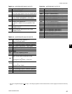
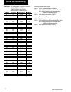
Following is the order of digital outputs that will appear
as the ENTER/ADV key is pressed:\
SYS 1 COMPRESSOR 1
SYS 1 LIQUID LINE SOLENOID VALVE
SYS 1 COMPRESSOR 2
SYS 1 COMPRESSOR 3
SYS 1 HOT GAS BYPASS SOLENOID VALVE
SYS 2 COMPRESSOR 1
SYS 2 LIQUID LINE SOLENOID VALVE
SYS 2 COMPRESSOR 2
SYS 2 COMPRESSOR 3
SYS 1 FAN STAGE 1
SYS 1 FAN STAGE 2
SYS 1 FAN STAGE 3
SYS 2 FAN STAGE 1
SYS 2 FAN STAGE 2
SYS 2 FAN STAGE 3
EVAPORATOR HEATER
SYS 1 ALARM
SYS 2 ALARM
EVAPORATOR PUMP
SYS 1 & 2 ACCUM RUN TIME/STARTS
Each display will also show the output connection on
the microboard for the respective digital output status
shown. For example:
This display indicates that the system 1 liquid line sole-
noid valve is OFF, and the output connection from the
microboard is coming from terminal block 3 - pin 2.
Pressing the UP Arrow key will energize the liquid line
solenoid valve and OFF will change to ON in the dis-
play as the LLSV is energized.
The last display shown on the above list is for the accu-
mulated run and start timers for each system. These
values can also be changed using the UP and Down
ARROW keys, but under normal circumstances would
not be advised.
1 INITIALIZE HISTORY
ENTER = YES
SOFTWARE VERS ION
C.MMC.01.01
SYS 1 LLSV STATUS
TB3 - 2 I S OFF
3