


YORK INTERNATIONAL
76
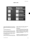
Pressing the COOLING SETPOINTS key a second time
will display the remote setpoint and cooling range. This
display automatically updates about every 2 seconds.
Notice that these setpoints are not “locally” program-
mable, but are controlled by a remote device such as
an ISN control. These setpoints would only be valid if
the unit was operating in the REMOTE mode.
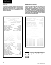
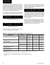
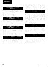
The messages below illustrate both leaving chilled liq-
uid control and return chilled liquid control respectively
(leaving chilled liquid control)
(return chilled liquid control)
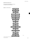
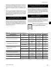
The low limit, high limit, and default values for the keys
under “SETPOINTS” are listed in Table 28.
REM SETP = 44 . 0 ° F
RANGE = + / - 2 . 0 ° F
REM SETP = 44 . 0 ° F
RANGE = 1 0 . 0 ° F
* Refer to Engineering Guide for operation below 30°F (-1.1°C). Alternate thermal expansion valves must be used
below 30°F (-1.1°C).
* When using glycol, Leaving Chilled Liquid Setpoint should not be set below 20°F (-6.7°C).
** Do not exceed 55°F (12.8°C) setpoint before contacting the nearest York Office for application
guidelines.
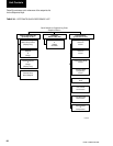
TABLE 28 – COOLING SETPOINTS PROGRAMMABLE LIMITS AND DEFAULTS
SETPOINT KEY MODEL LOW LIMIT HIGH LIMIT DEFAULT
LEAVING CHILLED LIQUID SETPOINT
WATER COOLING
40.0°F **70.0°F 44.0°F
4.4°C 21.1°C 6.7°C
GLYCOL COOLING
*10.0°F **70.0°F 44.0°F
-12.2°C 21.1°C 6.7°C
LEAVING CHILLED LIQUID
—
1.5°F 2.5°F 2.0°F
CONTROL RANGE 0.8
°C 1.4°C 1.1°C
RETURNED CHILLED LIQUID SETPOINT
WATER COOLING 40.0°F 70.0°F 44.0°F
4.4°C 21.1°C 6.7°C
GLYCOL COOLING
10.0°F 70.0°F 44.0°F
-12.2°C 21.1°C 6.7°C
RETURN CHILLED LIQUID
—
4.0°F 20.0°F 10.0°F
CONTROL RANGE 2.2°C 11.1°C 5.6°C
MAX EMS-PWM REMOTE
—
2°F40°F20°F
TEMPERATURE RESET 1.0°C 22.0°C 11.0°C
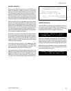
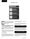
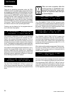
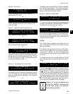
Pressing the COOLING SETPOINTS a third time will
bring up the display that allows the Maximum EMS-
PWM Temperature Reset to be programmed. This
message is shown below.
The Temp Reset value is the maximum allowable reset
of the temperature setpoint. The setpoint can be
reset
upwards by the use of a contact closure on the PWM
Temp Reset input (CTB1 terminals 13 - 20)). See the
section on Operating Controls for a detailed explana-
tion of this feature.
As with the other setpoints, the Up Arrow and Down
Arrow keys are used to change the Temp Reset value.
After using the UP and DOWN ARROWS to adjust to
the desired setpoint, the ENTER/ADV key must be
pressed to enter this number into memory.
M A X E M S - P W M R E M O T E
TEMP RESET = + 2 0° F
Unit Controls