


YORK INTERNATIONAL
68
EVAP PUMP I S ON
EVAP HEATER I S OFF
SYS X RUNT IME
XX-XX-XX-XX D-H-M-S
SYS X NUMBER OF
COMPS RUNN I NG X
SYS X LLSV I S ON
HOT GAS SOL I S OFF
SYS X FAN STAGE 3
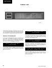
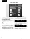
This display indicates the status of the evaporator pump
contacts and the evaporator heater.
The evaporator pump dry contacts are energized when
any compressor is running, or the unit is not OFF on
the daily schedule and the unit switch is on, or the unit
has shutdown on a Low Leaving Chilled Liquid fault.
However, even if one of above is true, the pump will not
run if the micro panel has been powered up for less
than 30 seconds or if the pump has run in the last 30
seconds to prevent pump motor overheating.
The evaporator heater is controlled by ambient air tem-
perature. When the ambient temperature drops below
40°F the heater is turned on. When the temperature rises
above 45°F the heater is turned off. An under voltage
condition will keep the heater off until full voltage is re-
stored to the system.
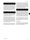
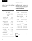
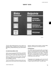
There are several types of remote systems that can be
used to control or monitor the unit. The following mes-
sages indicate the type of remote control mode active:
NONE – no remote control active. Remote monitoring
may be via ISN
ISN – YorkTalk via ISN (Remote Mode)
*LOAD LIM – load limiting enabled. Can be either stage
1 or stage 2 of limiting.
*PWM TEMP – EMS-PWM temperature reset
*Refer to the section on Operating Controls
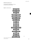
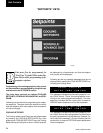
The above four message will appear sequentially, first
for system 1, then for system 2.
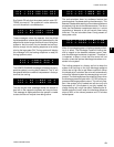
The first message indicates the system and number of
compressors that are being commanded on by the mi-
cro board.
The second message indicates the system run time in
days – hours – minutes – seconds. Please note that this
is not accumulated run time but pertains only to the cur-
rent system cycle.
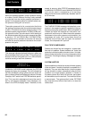
The third message indicates the system, and whether
the liquid line solenoid and hot gas solenoid are being
commanded on by the micro board. Please note that
hot gas in not available for system 2, so there is no mes-
sage pertaining to the hot gas solenoid when system 2
message is displayed.
The fourth message indicates what stage of condenser
fan operation is active. Unless a low ambient kit is added,
only stages 1 and 2 will be used to cycle the condenser
fans. However, stage 3 may be shown in this display
without a low ambient kit added, but it has no effect.
See the section on Condenser Fan Control in the Unit
Operation section.
ACT I VE REMOTE CTRL
NONE
Unit Controls