


YORK INTERNATIONAL
12
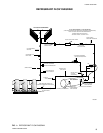
Hand stop valves should be installed in all lines to facili-
tate servicing.
Piping to the inlet and outlet connections of the chiller
should include high-pressure rubber hose or piping loops
to insure against transmission of water pump vibration.
The necessary components must be obtained in the
field.
Drain connections should be provided at all low points
to permit complete drainage of the cooler and system
water piping.
A small valve or valves should be installed at the high-
est point or points in the chilled water piping to allow
any trapped air to be purged. Vent and drain connec-
tions should be extended beyond the insulation to make
them accessible.
The piping to and from the cooler must be designed to
suit the individual installation. It is important that the
following considerations be observed:
1. The chilled liquid piping system should be laid out so
that the circulating pump discharges directly into the
cooler. The suction for this pump should be taken
from the piping system return line and not the cooler.
This piping scheme is recommended, but is not man-
datory.
2. The inlet and outlet cooler connection sizes are 3"
(YCAL0014 - 0030), 4" (YCAL0034 - 0060), or 6"
(YCAL0064 - 0080).
3. A strainer, preferably 40 mesh, must be installed in
the cooler inlet line just ahead of the cooler. This is
important to protect the cooler from entrance of large
particles which could cause damage to the evapora-
tor.
4. All chilled liquid piping should be thoroughly flushed
to free it from foreign material before the system is
placed into operation. Use care not to flush any for-
eign material into or through the cooler.
5. As an aid to servicing, thermometers and pressure
gauges should be installed in the inlet and outlet wa-
ter lines.
6. The chilled water lines that are exposed to outdoor
ambients should be wrapped with supplemental
heater cable and insulated to protect against freeze-
up during low ambient periods, and to prevent for-
mation of condensation on lines in warm humid lo-
cations.
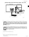
7. A chilled water flow switch, (either by YORK or oth-
ers) MUST be installed in the leaving water piping of
the cooler. There should be a straight horizontal run
of at least 5 diameters on each side of the switch.
Adjust the flow switch paddle to the size of the pipe
in which it is to be installed. (See manufacturer’s in-
structions furnished with the switch.) The switch is to
be wired to terminals 13 – 14 of CTB1 located in the
control panel, as shown on the unit wiring diagram.
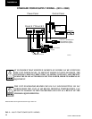
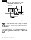
WIRING
Liquid Chillers are shipped with all factory mounted con-
trols wired for operation.
Field Wiring – Power wiring must be provided through
a fused disconnect switch to the unit terminals (or op-
tional molded disconnect switch) in accordance with
N.E.C. or local code requirements. Minimum circuit
ampacity and maximum dual element fuse size are given
in the Tables 2 – 6.
A 120-1-60, 15 amp source must be supplied for the
control panel through a fused disconnect when a con-
trol panel transformer (optional) is not provided. Refer
to Table 1 and Figures 2 - 4.
See Figures 2 - 5 and unit wiring diagrams for field and
power wiring connections, chilled water pump starter
contacts, alarm contacts, compressor run status con-
tacts, PWM input, and load limit input. Refer to section
on UNIT OPERATION for a detailed description of op-
eration concerning aforementioned contacts and inputs.
Installation
The Flow Switch MUST NOT be used
to start and stop the chiller (i.e. start-
ing and stopping the chilled water
pump). It is intended only as a safety
switch.