


YORK INTERNATIONAL
85
FORM 150.62-NM1
CAPACITY CONTROL
To initiate the start sequence of the chiller, all run per-
missive inputs must be satisfied (flow/remote start/stop
switch), and no chiller or system faults exist.
The first phase of the start sequence is initiated by the
Daily Schedule Start or a Remote Cycling Device. If the
unit is shut down on the daily schedule, the chilled wa-
ter pump microboard contacts (TB5 3-4) will close when
the daily schedule start time has been reached. Once
flow has been established and the flow switch closes,
capacity control functions are initiated.
If unit cycling is accomplished with a remote cycling
device wired in series with the flow switch, the chilled
water pump contacts will always be energized as long
as the unit switch is turned on. When the flow switch
and remote cycling contacts are closed, the capacity
control functions will be initiated.
It should be noted that the chilled water pump contacts
(TB5 3-4) are not required to be used to cycle the chilled
water pump. However, in all cases the flow switch must
be closed to allow unit operation.
The control system will evaluate the need for cooling by
comparing the actual leaving or return chilled liquid tem-
perature to the desired setpoint, and regulate the leav-
ing or return chilled liquid temperature to meet that de-
sired setpoint.
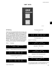
LEAVING CHILLED LIQUID CONTROL
The setpoint, when programmed for Leaving Chilled Liq-
uid Control, is the temperature the unit will control to
within +/- the cooling range. The Setpoint High Limit is
the Setpoint plus the Cooling Range. The Setpoint Low
Limit is the Setpoint minus the Cooling Range. See Fig-
ure 6.
If the leaving chilled liquid temperature is above the
Setpoint High Limit, the lead compressor on the lead
system will be energized along with the liquid line sole-
noid. Upon energizing any compressor, the 60 second
Anti-Coincidence timer will be initiated.
If after 60 seconds of run-time the leaving chilled liquid
temperature is still above the Setpoint High Limit, the
next compressor in sequence will be energized. Addi-
tional loading stages are energized at a rate of once
every 60 seconds if the chilled liquid temperature re-
mains above the Setpoint High Limit. In this case, the
load timer will be 60 seconds.
If the chilled liquid temperature falls below the Setpoint
High Limit but is greater than the Setpoint Low Limit,
loading and unloading do not occur. This area of con-
trol is called the control range.
If the chilled liquid temperature drops to less than 0.5°F
(.28°C) below the Setpoint Low Limit, unloading occurs
at a rate of 60 seconds. If the chilled liquid temperature
falls to a value greater than 0.5°F (.28°C) below the
Setpoint Low Limit but not greater than 1.5°F (.83°C)
below the Setpoint Low Limit, unloading occurs at a rate
of 30 seconds. If the chilled liquid temperature falls to a
value greater than 1.5°F (.83°C) below the Setpoint Low
Limit, unloading occurs at a rate of 20 seconds.
The leaving chilled liquid setpoint is programmable from
40°F to 70°F (4.4°C to 21.1°C) in water chilling mode
and from 10°F to 70°F (-12.2°C to 21.1°C) in glycol chill-
ing mode. In both modes, the cooling range can be from
+/-1.5°F to +/-2.5°F (+/-.83°C to 1.39°C).
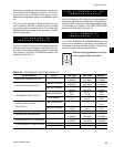
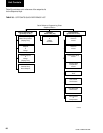
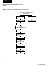
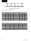
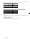
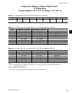
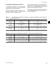
The sequences of Capacity Control (compressor stag-
ing) for loading and unloading are shown in Table 32
through Table 35.
UNIT OPERATION
2