


YORK INTERNATIONAL
103
FORM 150.62-NM1
KEYPAD
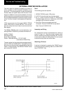
The operator keypad is connected to the microboard
by a ribbon cable, which is connected to J2 on the mi-
croboard.
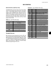
The integrity of a specific “button” on the keypad can be
verified by doing a continuity check across two specific
.
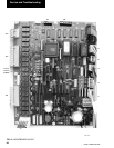
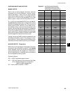
FIG. 9 – MICROBOARD RELAY CONTACT
ARCHITECTURE
LD03842
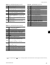
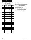
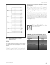
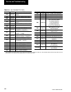
TABLE 49 – KEYPAD PIN ASSIGNMENT MATRIX
KEYPAD PIN CONNECTIONS
STATUS 1 TO 5
OPER DATA 1 TO 7
PRINT 1 TO 6
HISTORY 1 TO 8
UP ARROW 2 TO 5
DOWN ARROW 2 TO 7
ENTER/ADV 2 TO 6
COOLING SETPOINTS 2 TO 8
SCHEDULE/ADVANCE DAY 3 TO 5
PROGRAM 3 TO 7
OPTIONS 3 TO 6
CLOCK 3 TO 8
3
points (or pins), that represent one of twelve “buttons”
on the keypad.
Table 49 lists the key/pin assignments for the keypad.
Power to the microboard must be turned off, and
the ribbon cable disconnected from the microboard
prior to conducting the tests, or component dam-
age may result.
After the ribbon cable is disconnected from microboard,
ohmmeter leads are connected to the pins represent-
ing the specific “button” to be tested. After connecting
the meter leads, the “button” being checked is pressed
and a reading of zero ohms should be observed. After
releasing the “button”, the resistance value should be
infinite (open circuit).
Pin 1 is usually identified by a stripe
on the ribbon cable