


YORK INTERNATIONAL
11
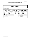
FORM 150.62-NM1
FOUNDATION
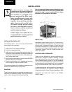
The unit should be mounted on a flat and level founda-
tion, floor, or rooftop capable of supporting the entire
operating weight of the equipment. See PHYSICAL
DATA for operating weight. If the unit is elevated be-
yond the normal reach of service personnel, a suitable
catwalk must be capable of supporting service person-
nel, their equipment, and the compressors.
GROUND LEVEL LOCATIONS
It is important that the units be installed on a substantial
base that will not settle. A one piece concrete slab with
footers extended below the frost line is highly recom-
mended. Additionally, the slab should not be tied to the
main building foundations as noise and vibration may
be transmitted. Mounting holes are provided in the steel
channel for bolting the unit to its foundation. (See DI-
MENSIONS.)
For ground level installations, precautions should be
taken to protect the unit from tampering by or injury to
unauthorized persons. Screws and/or latches on access
panels will prevent casual tampering. However, further
safety precautions such as a fenced-in enclosure or
locking devices on the panels may be advisable.
ROOFTOP LOCATIONS
Choose a spot with adequate structural strength to safely
support the entire weight of the unit and service per-
sonnel. Care must be taken not to damage the roof.
Consult the building contractor or architect if the roof is
bonded. Roof installations should have wooden beams
(treated to reduce deterioration), cork, rubber, or vibra-
tion isolators under the base to minimize vibration.
NOISE SENSITIVE LOCATIONS
Efforts should be made to assure that the chiller is not
located next to occupied spaces or noise sensitive ar-
eas where chiller noise level would be a problem. Chiller
noise is a result of compressor and fan operation. Con-
siderations should be made utilizing noise levels pub-
lished in the YORK Engineering Guide for the specific
chiller model. Sound blankets for the compressors and
low sound fans are available.
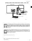
SPRING ISOLATORS (OPTIONAL)
When ordered, four (4) isolators will be furnished.
Identify the isolator, and locate at the proper mounting
point, and adjust per instructions. See Appendix 1.
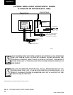
COMPRESSOR MOUNTING
The compressors are mounted on four (4) rubber isola-
tors. The mounting bolts should not be loosened or ad-
justed at installation of the chiller.
REMOTE COOLER OPTION
For units using remote cooler option, refer to instruc-
tions included with miscellaneous cooler parts kit.
The unit is shipped with a 6 lb. (2.7 kg) holding charge.
The remainder of the charge must be weighed-in ac-
cording to the operating charge listed under Physical
Data. Additional charge must also be added for the re-
frigerant lines.
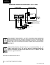
CHILLED WATER PIPING
General – When the unit has been located in its final
position, the unit water piping may be connected. Nor-
mal installation precautions should be observed in or-
der to receive maximum operating efficiencies. Piping
should be kept free of all foreign matter. All chilled wa-
ter evaporator piping must comply in all respects with
local plumbing codes and ordinances.
Since elbows, tees and valves decrease pump capac-
ity, all piping should be kept as straight and as simple
as possible possible. All piping must be supported
independent of the chiller.
Consideration should be given to com-
pressor access when laying out water
piping. Routing the water piping too
close to the unit could make compres-
sor servicing/replacement difficult.
1