


YORK INTERNATIONAL
102
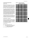
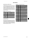
The suction transducers have a range from 0 to 200
PSIG (13.79 BARG). The output will be linear from .5
VDC to 4.5 VDC over the 200 PSIG (13.79 BARG)
range. Following is a formula that can be used to verify
the voltage output of the transducer. All voltage reading
are in reference to ground (unit case).
V = (Pressure in PSIG x .02) + .5
or
V = (Pressure in BARG x .29) + .5
where V = dc voltage input to micro
Pressure = pressure sensed by transducer
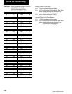
Following are the microboard connections for the Suc-
tion Transducer:
System 1 Suction Transducer
J4-5 = +5VDC regulated supply to transducer.
J4-10 = VDC input signal to the microboard. See
the formula above for voltage readings that
correspond to specific suction pressures.
J4-1 = +5VDC return
J4-2 = drain (shield connection = 0VDC)
System 2 Suction Transducer
J7-5 = +5VDC regulated supply to transducer.
J7-10 = VDC input signal to the microboard. See
the formula above for voltage readings that
correspond to specific suction pressures.
J7-1 = +5VDC return
J7-2 = drain (shield connection = 0VDC)
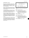
If the optional Suction Transducer is not used on the
YCAL0014 - YCAL0060, a Low Pressure switch will be
used. Following are the microboard connections for the
Low Pressure switch.
System 1 Low Pressure Switch
J4-5 = +5VDC regulated supply to LP switch.
J4-10 = input signal to the microboard. 0VDC =
open switch / +5 VDC = closed switch.
J4-2 = drain (shield connection = 0VDC)
System 2 Low Pressure Switch
J7-5 = +5VDC regulated supply to LP switch.
J7-10 = input signal to the microboard. 0VDC = open
switch / +5VDC = closed switch.
J7-2 = drain (shield connection = 0VDC)
DIGITAL OUTPUTS
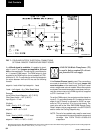
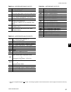
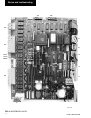
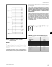
Refer to the unit wiring diagram and Table 46. The digi-
tal outputs are located on TB3, TB4, and TB5 of the
microboard. ALL OUTPUTS ARE 120VAC with the ex-
ception of TB5-3 to TB5-4. TB5-3 to TB5-4 are the con-
tacts that can be used for an evaporator pump start sig-
nal. The voltage applied to either of these terminals would
be determined by field wiring.
Each output is controlled by the microprocessor by
switching 120VAC to the respective output connection
energizing contactors, evap. heater, and solenoids ac-
cording to the operating sequence.
120 vac is supplied to the microboard via connections
at TB3-1, TB3-7, TB4-3, and TB4-7. Figure 9 illustrates
the relay contact architecture on the microboard.
Service and Troubleshooting