


YORK INTERNATIONAL
108
MAINTENANCE
It is the responsibility of the equipment owner to pro-
vide maintenance on the system.
IMPORTANT
If system failure occurs due to improper maintenance
during the warranty period, YORK will not be liable for
costs incurred to return the system to satisfactory op-
eration. The following is intended only as a guide and
covers only the chiller unit components. It does not cover
other related system components which may or may
not be furnished by YORK. System components should
be maintained according to the individual manufacture’s
recommendations as their operation will affect the op-
eration of the chiller.
COMPRESSORS
Oil Level check:
The oil level can only be tested when the compressor is
running in stabilized conditions, to ensure that there is
no liquid refrigerant in the lower shell of the compres-
sor. When the compressor is running at stabilized con-
ditions, the oil level must be between 1/4 and 3/4 in
the oil sight glass. Note: at shutdown, the oil level can
fall to the bottom limit of the oil sight glass. Use YORK
“F” oil when adding oil.
Oil Analysis:
The oil used in these compressors is pale yellow in color
(mineral oil). If the oil color darkens or exhibits a change
in color, this may be an indication of contaminants in
the refrigerant system. If this occurs, an oil sample
should be taken and analyzed. If contaminants are
present, the system must be cleaned to prevent com-
pressor failure.
Never use the scroll compressor to
pump the refrigerant system down into
a vacuum. Doing so will cause inter-
nal arcing of the compressor motor
which will result in failure of compres-
sor.
CONDENSER FAN MOTORS
Condenser fan motors are permanently lubricated and
require no maintenance.
CONDENSER COILS
Dirt should not be allowed to accumulate on the con-
denser coil surfaces. Cleaning should be as often as
necessary to keep coil clean.
Exercise care when cleaning the coil
so that the coil fins are not damaged.
OPERATING PARAMETERS
Regular checks of the system should be preformed to
ensure that operating temperatures and pressures are
within limitations, and that the operating controls are
set within proper limits. Refer to the Operation, Start-
Up, and Installation sections of this manual.
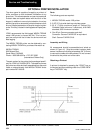
ON-BOARD BATTERY BACK-UP
U17 is the Real Time Clock chip that maintains the date/
time and stores customer programmed setpoints. Any-
time the chiller is to be off (no power to the microboard)
for an extended time (weeks/months), the clock should
be turned off to conserve power of the on-board bat-
tery. To accomplish this, the J11 jumper on the micro-
board must be moved to the “CLKOFF” position while
power is still supplied to the microboard.
THE UNIT EVAPORATOR HEATER
IS 120 VAC. DISCONNECTING
120VAC POWER FROM THE UNIT,
AT OR BELOW FREEZING TEM-
PERATURES, CAN RESULT IN
DAMAGE TO THE EVAPORATOR
AND UNIT AS A RESULT OF THE
CHILLED LIQUID FREEZING.
OVERALL UNIT INSPECTION
In addition to the checks listed on this page, periodic
overall inspections of the unit should be accomplished
to ensure proper equipment operation. Items such as
loose hardware, component operation, refrigerant leaks,
unusual noises, etc. should be investigated and cor-
rected immediately.
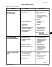
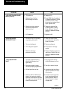
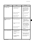
Service and Troubleshooting