


YORK INTERNATIONAL
101
FORM 150.62-NM1
ANALOG INPUTS – Pressure
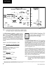
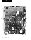
Refer to the unit wiring diagram. Pressure inputs are
connected to the microboard on plugs J4 and J7. These
analog
inputs represent varying dc signals correspond-
ing to varying pressures. All voltages are in reference
to the unit case (ground).
System 1 discharge and suction pressures will be con-
nected to J4 of the microboard. System 2 discharge
and suction pressure transducers will be connected to
J7 of the microboard.
The discharge transducers are optional on all units. If
the discharge transducers are not installed, no connec-
tions are made to the microboard and the discharge
pressure readout on the display would be zero.
The suction pressure transducers are optional on
YCAL0014 - YCAL0060. If the suction transducers are
not installed, a mechanical low pressure switch will be
installed in its place, and the suction pressure readout
on the display will be 0 PSIG when the LP switch is
open, and 200 PSIG (13.79 BARG) when the LP switch
is closed.
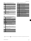
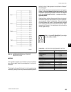
The discharge transducers have a range from 0 to 400
PSIG. The output will be linear from .5VDC to 4.5VDC
over the 400 PSIG (27.5 BARG) range. Following is the
formula that can be used to verify the voltage output of
the transducer. All voltage reading are in reference to
ground (unit case).
V = (Pressure in PSIG x .01) + .5
or
V = (Pressure in BARG x .145) + .5
where V = dc voltage output
Pressure = pressure sensed by transducer
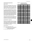
The microboard connections for the Discharge Trans-
ducers:
System 1 Discharge Transducer
J4-7 = +5VDC regulated supply to transducer.
J4-12 = VDC input signal to the microboard. See the
formula above for voltage readings that
correspond to specific discharge pressures.
J4-8 = +5VDC return
J4-9 = drain (shield connection = 0VDC)
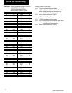
System 2 Discharge Transducer
J7-7 = +5VDC regulated supply to transducer.
J7-12 = VDC input signal to the microboard. See the
formula above for voltage readings that
correspond to specific discharge pressures.
J7-8 = +5VDC return
J7-9 = drain (shield connection = 0VDC)
3