


YORK INTERNATIONAL
63
FORM 150.62-NM1
The Discharge Pressure Cutout is a software cutout in
the microprocessor and is backed-up by a mechanical
high pressure cutout switch located in the refrigerant
circuit. It assures that the system pressure does not
exceed safe working limits. The system will shutdown
when the programmable cutout is exceeded and will
be allowed to restart when the discharge pressure falls
below the cutout.
Discharge transducers must be in-
stalled for this function to operate.
The Suction Pressure Cutout is a software cutout that
protects the chiller from an evaporator freeze-up should
the system attempt to run with a low refrigerant charge
or a restriction in the refrigerant circuit.
At system start, the cutout is set to 10% of programmed
value. During the next 3 minutes the cutout point is
ramped up to the programmed cutout point. If at any
time during this 3 minutes the suction pressure falls
below the ramped cutout point, the system will stop.
This cutout is ignored for the first 90 seconds of sys-
tem run time to avoid nuisance shutdowns, especially
on units that utilize a low pressure switch in place of
the suction pressure transducer.
After the first 3 minutes, if the suction pressure falls
below the programmed cutout setting, a “transient pro-
tection routine” is activated. This sets the cutout at 10%
of the programmed value and ramps up the cutout over
the next 30 seconds. If at any time during this 30 sec-
onds the suction pressure falls below the ramped cut-
out, the system will stop. This transient protection
scheme only works if the suction pressure transducer
is installed. When using the mechanical LP switch, the
operating points of the LP switch are: opens at 23 PSIG
+/- 5 PSIG (1.59 barg +/- .34 barg), and closes at 35
PSIG +/- 5 PSIG (2.62 barg +/- .34 barg).
The Motor Protector/Mechanical High Pressure Cutout
protect the compressor motor from overheating or the
system from experiencing dangerously high discharge
pressure. This fault condition is present when CR1 (SYS 1)
or CR2 (SYS 2) relays de-energize due to the HP switch
or the motor protector opening. This causes the respec-
tive CR contacts to open causing 0 VDC to be read on
the inputs to the microboard. The fault condition is
cleared when a 30 VDC signal is restored to the input.
The internal motor protector opens at 185°F - 248°F
(85°C - 120°C) and auto resets. The mechanical HP
switch opens at 405 PSIG +/- 10 PSIG (27.92 barg +/-
.69 barg) and closes at 330 PSIG +/- 25 PSIG (22.75
barg +/- 1.72 barg).
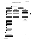
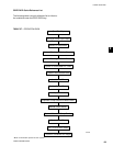
UNIT SAFETIES
Unit safeties are faults that cause all running compres-
sors to be shut down. Unit faults are auto reset faults in
that the unit will be allowed to restart automatically after
the fault condition is no longer present.
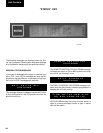
SYS 1 H IGH DSCH PRES
SYS 2 H IGH DSCH PRES
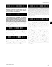
SYS 1 LOW SUCT PRESS
SYS 2 LOW SUCT PRESS
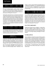
SYS 1 MP/ HPCO FAULT
SYS 2 MP/ HPCO FAULT
2