


YORK INTERNATIONAL
92
PUMPDOWN (LLSV) CONTROL
Each system has a Pumpdown feature upon shut-off.
On a non-safety, non-unit switch shutdown, all compres-
sors but one in the system will be shut off. The LLSV
will also be turned off. The final compressor will be al-
lowed to run until the suction pressure falls below the
cutout or for 180 seconds, which ever comes first.
Manual pumpdown from the keypad is not possible.
LOAD LIMITING
Load Limiting is a feature that prevents the unit from
loading beyond the desired value. 2 and 4 compressor
units can be load limited to 50%. This would allow only
1 compressor per system to run. 3 and 6 compressor
units can be load limited to 33% or 66%. The 66% limit
would allow up to 2 compressors per system to run,
and the 33% limit would allow only 1 compressor per
system to run. No other values of limiting are available.
There are two ways to load limit the unit. The first is
through remote communication via an ISN.
A second way to load limit the unit is through closing
contacts connected to the Load Limit (CTB1-Terminals
13-21) and PWM inputs (CTB1-Terminals 13-20). Stage
1 of load limiting involves closing the Load Limit input.
Stage 2 of load limiting involves closing both the Load
Limit and PWM inputs. The first stage of limiting is ei-
ther 66% or 50%, depending on the number of com-
pressors on the unit. The second stage of limiting is
33% and is only available on 3 and 6 compressor units.
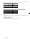
Table 43 shows the load limiting permitted for the vari-
ous number of compressors.
NOTE: Simultaneous operation of Load Limiting and
EMS-PWM Temperature Reset (described on
following pages) cannot occur.
COMPRESSOR RUN STATUS
Compressor run status is indicated by closure of con-
tacts at CTB2 – terminals 25 to 26 for system 1 and
CTB2 – terminals 27 to 28 for system 2.
ALARM STATUS
System or unit shutdown is indicated by normally-open
alarm contacts opening whenever the unit shuts down
on a unit fault, or locks out on a system fault. System 1
alarm contacts are located at CTB2 - terminals 29 to
30. System 2 alarm contacts are located at CTB2 - ter-
minals 31 to 32. The alarm contacts will close when
conditions allow the unit to operate.
COMPRESSOR SEQUENCING
The unit control will attempt to equalize the total run
hours on individual compressors within a system. When
a system is about to start, the compressor with the least
run time in that system will be the first to start. When
the system has to load, the next compressor to start
will be the one with the least run time that is currently
not running in that system.
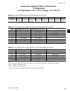
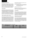
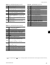
TABLE 43 – COMPRESSOR OPERATION – LOAD LIMITING
COMPRESSORS IN UNIT STAGE 1 STAGE 2
2 50% –
3 66% 33%
4 50% –
6 66% 33%
Unit Controls