


YORK INTERNATIONAL
54
PRE-STARTUP CHECKLIST
G 8. Visually inspect wiring (power and control). Wir-
ing MUST meet N.E.C. and local codes. See Fig-
ures 2- 5, pages 14 - 17.
G 9. Check tightness of power wiring inside the power
panel on both sides of the motor contactors and
overloads.
G10. Check for proper size fuses in main and control
circuits, and verify overload setting corresponds
with RLA and FLA values in electrical tables.
G11. Assure 120VAC Control Power to CTB2 has 15
AMP minimum capacity. See Table 1, page 20.
G12. Be certain all water temp sensors are inserted
completely in their respective wells and are
coated with heat conduc-
tive compound.
G13. Assure that evaporator TXV bulbs are strapped
onto the suction lines at 4 or 8 o’clock positions.
PANEL CHECKS
(POWER ON – BOTH UNIT SWITCH OFF)
G 1. Apply 3-phase power and verify its value. Volt-
age imbalance should be no more than 2% of the
average voltage.
G 2. Apply 120VAC and verify its value on the termi-
nal block in the Power Panel. Make the measure-
ment between terminals 5 and 2 of CTB2. The
voltage should be 120VAC +/- 10%.
JOB NAME: ______________________________
SALES ORDER #: _________________________
LOCATION: _______________________________
SOLD BY: ________________________________
INSTALLING
CONTRACTOR: ___________________________
START-UP
TECHNICIAN/
COMPANY: _______________________________
START-UP DATE : _________________________
CHILLER MODEL #: _______________________
SERIAL #: ________________________________
CHECKING THE SYSTEM
PRIOR TO INITIAL START (NO POWER)
Unit Checks
G 1. Inspect the unit for shipping or installation
damage.
G 2. Assure that all piping has been completed.
G 3. Visually check for refrigerant piping leaks.
G 4. Open suction line ball valve, discharge line
ballvalve, and liquid line valve for each system.
G 5.The compressor oil level should be maintained so
that an oil level is visible in the sight glass.The oil
level can only be tested when the compressor is
running in stabilized conditions, guaranteeing that
there is no liquid refrigerant in the lower shell of
the compressor. In this case, the oil should be
between 1/4 and 3/4 in the sight glass. At shut-
down, the oil level can fall to the bottom limit of
the oil sight glass.
G 6. Assure water pumps are on. Check and adjust
water pump flow rate and pressure drop across
the cooler (see LIMITATIONS). Verify flow switch
operation.
Excessive flow may cause catastrophic
damage to the evaporator.
G 7. Check the control panel to assure it is free of
foreign material (wires, metal chips, etc.).
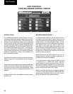
OPTIONS
Display Language
Sys 1 Switch
Sys 2 Switch
Unit Type
Chilled Liquid
Ambient Control
Local/ Remote Mode
Control Mode
Display Units
Lead/Lag Control
Fan Control
Manual Override
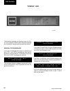
COOLING SETPOINTS
Cooling Setpoint
Range
EMS-PWM Max. Setpoint
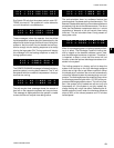
PROGRAM
Discharge Pressure Cutout
Suct. Pressure Cutout
Low Amb. Temp. Cutout
Leaving Liquid Temp. Cutout
Anti-Recycle Time
Fan Control On-Pressure
Fan Differential Off-Pressure
Total # of Compressors
TABLE 25 – SETPOINTS
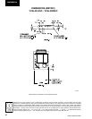
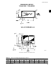
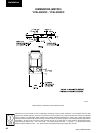
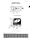
Installation