


71Part number 550-141-850/0699
• Installation • Start-Up • Parts • Maintenance
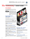
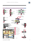
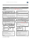
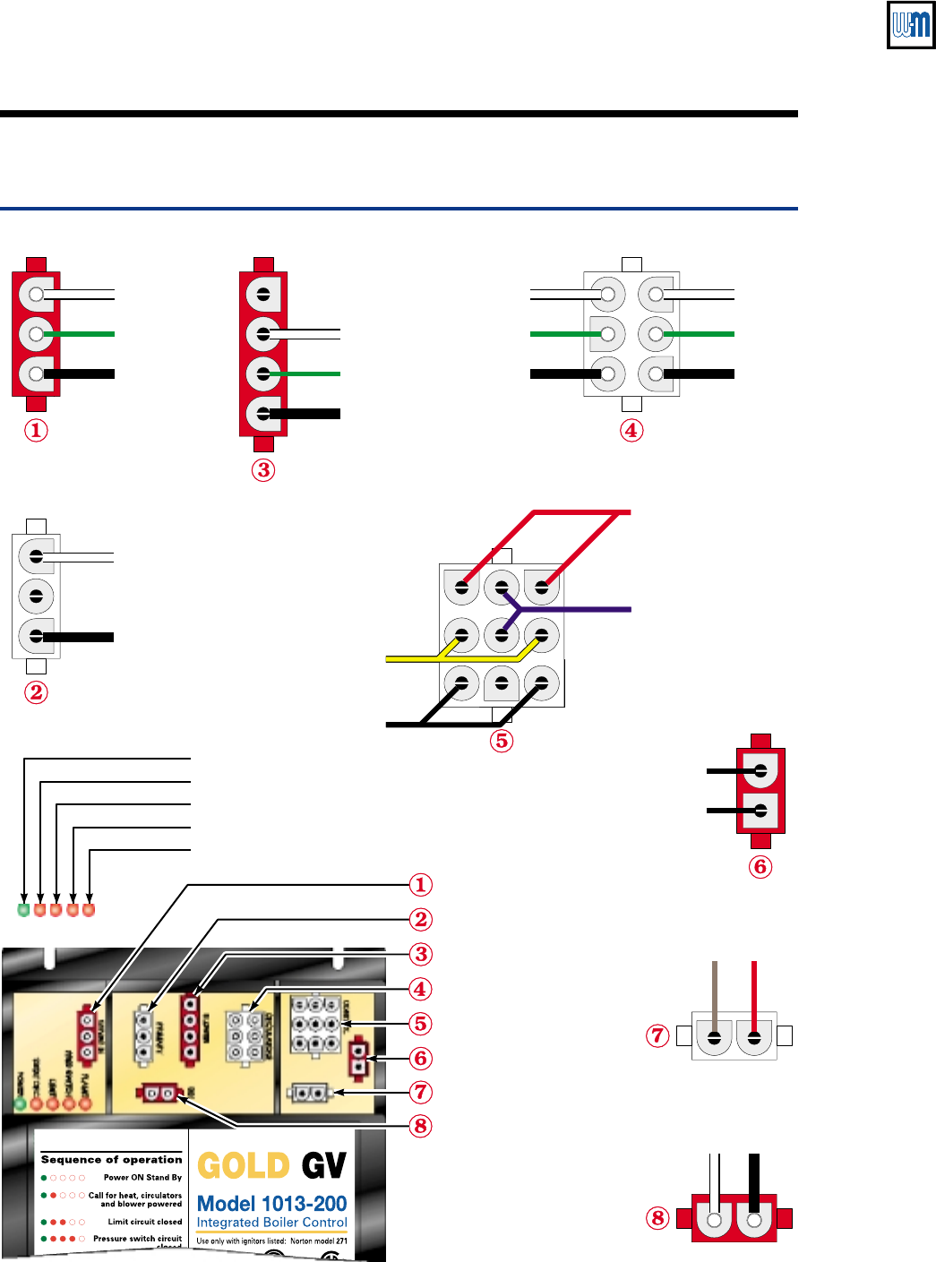
Indicator lights
POWER
TSTAT CIRC
LIMIT
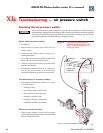
PRES SWITCH
FLAME
120 VAC IN
120 VAC IN
120 VAC H
120 VAC H
24 VAC
120 VAC H
120 VAC H
Red wires to
pressure switch
Blue wires to
gas valve
Yellow wires
to limit control
and block temp
switch
Black wires to
thermostat circuit
120 VAC H
120 VAC N
120 VAC N
120 VAC N
120 VAC N120 VAC N
Ground
GroundGround
120 VAC to transformer
120 VAC to
transformer
120 VAC to igniter
120 VAC to igniter
24 VAC from transformer
24 VAC from transformer
water temp sensor
24 VAC control circuits
24 VAC control
circuits
120 VAC to circulators
120 VAC
to circulators
White
White White
White
White
Brown
Green
Green Green
Black
Black Black
Black
Black
Red
to System
circulator
(long harness)
to Bypass
circulator
(short harness)
120 VAC to blower motor
120 VAC to
blower motor
120 VAC H
120 VAC N
Ground
White
Green
Black
Black leads
to water
temperature
sensor
water temp
sensor
85051
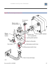
Figure 34 GCM (control module) harness plug receptacle and indicator light locations.