


Part number 550-141-850/069912
GOLD GV Water boiler series 3 — manualGOLD GV Water boiler series 3 — manual
GOLD GV Water boiler series 3 — manualGOLD GV Water boiler series 3 — manual
GOLD GV Water boiler series 3 — manual
Prepare boiler location — vent system
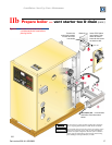
Vent system
The GV boiler requires a special vent system, designed
for pressurized venting with likelihood of condensation
in the vent. This is referred to as ANSI Z21 Class IV,
Condensing
.
You may use any of the vent systems covered by the GV
venting supplements included in the instruction manual
envelope. The GV vent starter tee is a special item designed
only for the GV boiler, available from each vendor. Do
not attempt to connect the vent to the GV boiler with any
other means.
DO NOT mix components from
different systems. The vent system
could fail, causing leakage of flue
products into the living space, causing
severe personal injury or death.
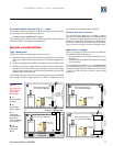
Vent termination and
combustion air supply
The GV boiler may be vented through the roof or through
a side wall. Follow the appropriate vent supplement for
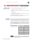
the vent system chosen. The maximum vent length
depends on boiler size. Refer to the vent supplement to
verify vent length will be acceptable.
Combustion air for the GV boiler may be from inside or
ducted directly to the boiler from outside. For outside air
(direct vent installation), two options are available for
the flue/air termination. The air supply must ALWAYS
terminate at the same location as the flue, using either:
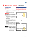
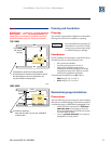
1. Vertical direct vent installation. Obtain the Through-
roof or through-unused chimney kit and
supplement. Find additional information in the vent
supplement for the venting material chosen.
2. Sidewall vent/air termination. This requires the Weil-
McLain GV vent/air intake termination kit. Refer
to the instructions packed with the kit and the vent
supplement for the venting material chosen.
Installations above 5,500 feet altitude must be
direct vent if sidewall vented.
Failure to follow all instructions
following can result in flue gas
spillage and carbon monoxide
emissions, causing severe personal
injury or death.
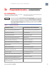
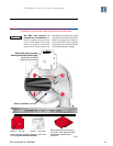
When removing a boiler
from an existing common vent system:
At the time of removal of an existing boiler, the following
steps shall be followed with each appliance remaining
connected to the common venting system placed in
operation, while the other appliances remaining connected
to the common venting system are not in operation.
a. Seal any unused openings in the common
venting system.
b. Visually inspect the venting system for proper
size and horizontal pitch and determine there is no
blockage or restriction, leakage, corrosion and other
deficiencies which could cause an unsafe condition.
c. Test vent system — Insofar as is practical, close
all building doors and windows and all doors between
the space in which the appliances remaining
connected to the common venting system are located
and other spaces of the building. Turn on clothes
dryers and any appliance not connected to the
common venting system. Turn on any exhaust fans,
such as range hoods and bathroom exhausts, so they
will operate at maximum speed. Do not operate a
summer exhaust fan. Close fireplace dampers.
d. Place in operation the appliance being inspected.
Follow the lighting instructions. Adjust thermostat
so appliance will operate continuously.
e. Test for spillage at draft hood relief opening after
5 minutes of main burner operation. Use the flame
of a match or candle, or smoke from a cigarette,
cigar, or pipe.
f. After it has been determined that each appliance
remaining connected to the common venting system
properly vents when tested as outlined above, return
doors, windows, exhaust fans, fireplace dampers, and
any other gas-burning appliance to their previous
conditions of use.
Any improper operation of common venting system
should be corrected so the installation conforms with
the National Fuel Gas Code, ANSI Z223.1 — latest edition.
Id
Removing from existing vent
Correct by resizing to approach the minimum size as
determined using the appropriate tables in Part 11 of
that code. Canadian installations must comply with CAN/
CGA B149.1 or B149.2 Installation Code.
GV special vent system