


Part number 550-141-850/069964
GOLD GV Water boiler series 3 — manualGOLD GV Water boiler series 3 — manual
GOLD GV Water boiler series 3 — manualGOLD GV Water boiler series 3 — manual
GOLD GV Water boiler series 3 — manual
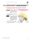
Service & maint. — special proced. (cont.)Xd
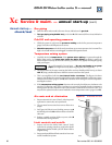
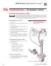
Cleaning boiler heating surfaces
The service procedures listed in Section IXc of this manual must only be performed by a qualified
boiler service technician. Failure to comply could result in severe personal injury, death or substantial
property damage.
7. Remove burner cone and gasket for inspection.
To clean heating surfaces
1. Replace flueway inspection port cover (page 3, item g).
2. Remove the corrugated drain tubing from the bottom
of the vent starter tee by releasing the tube clamp.
3. Place a catch pan under the tee to catch the cleaning
water.
4. Spray water into the boiler combustion chamber
opening.
5. Catch the runoff water in the pan below the vent
starter tee.
6. Continue process until flueways are clean.
1. If inspection of the boiler flueways indicates the
presence of soot, clean the boiler heating surfaces
using the following procedure. The process requires
removing the blower housing to allow spraying water
through the boiler combustion chamber.
Before proceeding, obtain a GV gasket replacement
kit, consisting of igniter, vent starter tee, flueway
inspection port and blower gaskets.
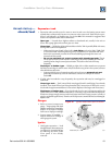
To remove the blower assembly
1. Turn off boiler by turning down the thermostat. Then
turn off power at the boiler service switch. Close
manual gas valve on incoming gas line to boiler.
Turn off power and gas to the boiler.
Failure to do so can cause severe
personal injury, death or substantial
property damage.
Wait several minutes after boiler has
stopped to allow the igniter to cool
to avoid severe personal injury or
death.
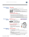
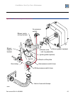
2. See Figure 32.
3. Disconnect:
• gas tubing from gas valve outlet (NOTE that
this is a left-hand thread
) by rotating the
hex fitting clockwise looking at the valve outlet.
• pressure switch hoses.
• air inlet hose.
• blower motor wiring harness from control
module.
• igniter harness connected to igniter plug.
• blower support bracket (remove screw
securing blower housing to bracket — on left
side of blower housing).
• ground wire.
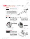
4. Remove the two igniter screws and washers. Carefully
remove the igniter. Use care when handling — igniter
is very brittle. DO NOT touch igniter surface with
hands or expose to any greasy substances.
5. Remove nuts from studs securing blower housing to
front section.
6. Grasp blower housing and pull free from studs. Turn
clockwise slightly, until blower assembly can be
removed safely from inside of boiler jacket.
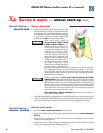
Replace blower assembly
1. Place a new blower housing gasket over the studs at
combustion chamber opening.
2. Reinstall burner cone into chamber opening.
3. Position blower assembly over studs. Install nuts and
tighten.
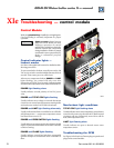
4. Install igniter and new igniter gasket. Fasten with
screws and washers. Tighten only with hand-held
screwdriver. DO NOT use electric or pneumatic
driver. Excessive torque will damage igniter. Do not
exceed 20 inch-pounds torque.
5. Connect:
a. gas tubing to gas valve outlet (turning left-
hand thread hex fitting counterclockwise to
tighten).
b. pressure switch hoses.
c. hose from gas valve to gas/air manifold.
d. air inlet hose.
e. blower motor wiring harness to control
module.
f. igniter harness to igniter plug.
g. blower support bracket (with screw).
h. ground wire.
6. Be sure all wiring and hose connections are correct
per Figure 32 and are secure on the hose barb fittings.