


Part number 550-141-850/069928
GOLD GV Water boiler series 3 — manualGOLD GV Water boiler series 3 — manual
GOLD GV Water boiler series 3 — manualGOLD GV Water boiler series 3 — manual
GOLD GV Water boiler series 3 — manual
Water piping — boiler connections
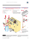
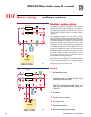
Supply & return connections
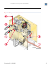
Always connect supply and return connections to the
boiler as shown in Figure 9. (Note in the following and in
the suggested piping drawings in this manual that the
expansion tank and air separator location will depend on
the system piping.)
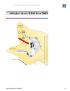
Air separator
Install an air separator in the piping as shown. For
single-zone systems, install the air separator in the return
piping as shown in Figure 9. This allows mounting the
automatic air vent and expansion tank off of the separator.
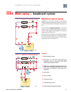
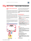
Expansion tank
Figures 9 and 10 show typical installation of the
expansion tank when the boiler is connected to a zone-
valve zoned baseboard system (see Figure 10). Always
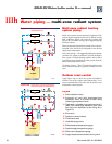
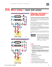
locate the air separator and expansion tank as shown in
the suggested piping drawings, Figures 10 through 16.
Ensure that the expansion tank size will handle boiler and
system water volume and temperature. See tank
manufacturer’s instructions and ratings for details.
Additional tanks may be added to the system if needed to
handle the expansion. These tanks may be installed by
connecting to tees in the system piping.
Undersized expansion tanks
cause system water to be lost from
the relief valve and makeup water to
be added through the fill valve.
Eventual section failure can result.
Always locate the cold water fill
connection
at the expansion tank.
Never locate this elsewhere in the
system.
Diaphragm- or bladder-type tank:
Refer to Figure 9 for suggested piping when using a
diaphragm- or bladder-type expansion tank.
Diaphragm- or bladder-type
expansion tank
— Control fill
pressure
with the tank air charge
pressure. Always check pressure and
charge tank with tank removed from
system to be sure reading is accurate.
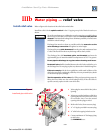
Boiler relief valve is set for 30 PSIG.
IIIc
Operating pressure of system, after
temperature expansion above cold fill
pressure, should not exceed 24 PSIG
to avoid weeping of relief valve.
Install an automatic air vent on top of the air separator,
per separator manufacturer’s instructions.
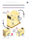
Closed-type expansion tank:
Figure 10 shows suggested piping when using a closed-
type expansion tank, in which the air is directly in contact
with tank water.
Connect piping (½" or ¾") from the air separator top
outlet to the tank fitting. Slope any horizontal piping a
minimum of 1 inch per 5 feet of horizontal pipe.
Always use a tank fitting, such as the B&G Tanktrol or
Taco Taco-Trol (shown). The fitting reduces gravity flow
of water in the piping to the tank, avoids air bubbling
through the tank water, and provides the proper fill height
in the tank.
Correct all leaks in the system or
tank piping. Leaks allow air to escape
from the system and will cause water-
logging of the tank. This will result in
water loss through the boiler relief
valve due to over-pressurization.
NEVER use an automatic air vent in
a system equipped with a closed-type
expansion tank. The air removed
from the system will cause water-
logging of the expansion tank.
Closed-type expansion tank —
Follow tank manufacturer’s
instructions for filling the tank.
Typical tank sizing provides for
approximately 12 PSIG when the
tank is filled to the normal level and
system water is cold. Note that boiler
relief valve is set for 30 PSIG.
Operating pressure of system, after
temperature expansion above cold fill
pressure, should not exceed 24 PSIG
to avoid weeping of relief valve.
Backflow preventer
Where required by codes, install a backflow preventer
in the cold water fill line, as shown in suggested piping
diagrams on following pages. Install a check valve if a
backflow preventer is not installed.