


Part number 550-141-850/069940
GOLD GV Water boiler series 3 — manualGOLD GV Water boiler series 3 — manual
GOLD GV Water boiler series 3 — manualGOLD GV Water boiler series 3 — manual
GOLD GV Water boiler series 3 — manual
Field wiringVI
Electrical installation must
comply with:
National Electrical Code and any other national, state,
provincial or local codes or regulations.
In Canada, C.S.A. C22.1 Canadian Electrical Code Part
1, and any local codes.
Wiring must be N.E.C. Class 1.
If original wiring as supplied with boiler must be replaced,
use only type 90 °C wire or equivalent.
Boiler must be electrically grounded as required by
National Electrical Code ANSI/NFPA 70-latest edition.
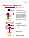
Wiring connections
Thermostat(s)
Install on inside wall away from influences of drafts, hot
or cold water pipes, lighting fixtures, television, sunrays,
or fireplaces.
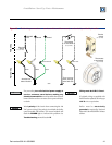
Follow instructions with thermostat. If it has a heat
anticipator, set heat anticipator in thermostat to match
power requirements of equipment connected to it (ignition
control and gas valve, zone valve contacts, etc.). Wiring
diagram on boiler gives setting for standard equipment
(ignition control and gas valve).
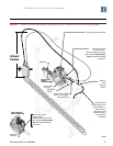
Thermostat wires are labeled "T-T" on boiler. Remove
label before connecting as shown in Figure 18. Route this
wiring through the hole in the upper left side jacket.
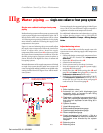
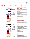
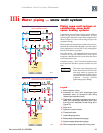
For zoned systems, substitute the zone valve end switches
or circulator relay contacts for the thermostat contact
shown in Figure 18.
When using three-wire zone valves,
take care to avoid miswiring.
This can impose an additional 24
volts across the boiler control
circuitry. The boiler control module
will sense this problem and lockout.
It will flash the POWER and TSTAT
CIRC
lights to indicate the problem.
See label on control module for
explanation of lockout conditions. To
verify before connecting to boiler,
disconnect field thermostat wires at
boiler. Place a voltmeter across the
leads. Then watch the voltmeter as
each zone is activated (by activating
zone thermostat). There should never
be a voltage reading across the two
leads coming to the boiler. If you see
a voltage reading, one or more zone
valves is miswired.
Junction Box (furnished)
Mount the 2 x 4 junction box on the left side of the boiler
as shown on page 3 of this manual and in other
illustrations.
Fused disconnect or service switch (15 amp.
recommended) may be mounted on this box. For those
installations with local codes which prohibit installation
of fused disconnect or service switch on boiler, install a
2 x 4 cover plate on the boiler junction box and mount
the service switch remotely as required by the code.
Connect 120 VAC power wiring as shown in Figure 18.