


Part number 550-141-850/069946
GOLD GV Water boiler series 3 — manualGOLD GV Water boiler series 3 — manual
GOLD GV Water boiler series 3 — manualGOLD GV Water boiler series 3 — manual
GOLD GV Water boiler series 3 — manual
Start-up — altitude over 5,500 feet ONLYVIIf
Apply the following only when:
• Altitude is over 5,500 feet above sea level.
• You have obtained a high altitude kit (with
tools needed) and installed high altitude air
pressure switch per the instructions of manual
Section
IId.
• Boiler has started correctly, following
procedures on previous pages.
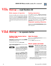
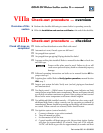
You will need the tools shown in Figure 20. Adjust the gas
valve outlet pressure only if required as described in the
following instructions.
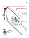
Connect and adjust manometer
1. Remove boiler jacket top and front.
2. Close manual gas supply valve and turn off electrical
power to boiler.
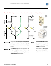
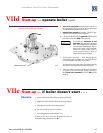
3. Using 3/16" allen wrench, remove outlet pressure tap
plug from gas control and save plug (Figure 21).
4. Install 1/8" NPT-to-hose barb fitting in gas control
outlet pressure tap as shown (Figure 21).
5. Position and zero manometer per manufacturer’s
instructions.
• Manometer must have at least 6" of tubing
above the fluid level or fluid may be drawn
into the gas control.
If manometer fluid is drawn into gas
control body, gas control must be
replaced. Fluid in valve will cause it
to malfunction, possibly resulting in
severe personal injury, death or
substantial property damage.
6. Disconnect tube from hose barb on gas control vent
tap. Connect tube end to tee hose fitting as shown in
Figure 21. Then add length of hose from tee hose
fitting to gas control vent tap.
7. Connect positive side manometer hose to top of the
tee hose fitting (Figure 21).
8. Connect negative side manometer hose to hose barb
fitting installed in gas control outlet pressure tap
(Figure 21).
Check Gas Control Set Point
1. Open manual gas valve and turn on electrical power
to boiler.
2. Start boiler and allow boiler to run for 5 minutes.
3. Read manometer. This is the gas control outlet
pressure set point. If set point is between – 0.1" w.c.
and – 0.3" w.c. go to step 7.
4. If gas control set point is not between – 0.1" w.c. and
– 0.3" w.c. remove cap on adjustment tower of gas
control.
• For White-Rodgers Model 36C valves, use
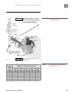
Figure 20 Tools required for gas valve outlet
pressure measurement
85025
1 U-tube manometer with tubing - Manometer provides a fine
scale by slanting the manometer (Dwyer Model 1227
recommended).
2 Tee hose fitting (provided in high altitude kit).
3 ³⁄₁₆ " allen wrench.
4 ¹⁄₈" N.P.T.-to-hose barb fitting and wrench for same. (Fitting
is provided in high altitude kit.)
5 Phillips screwdriver.
6 ¹⁄₄ " flat head screwdriver.
7 Special tool for gas control adjustment cap removal for
White-Rodgers 36C valves (provided in high altitude kit).
8 Pliers.
pliers and special tool provided (Figure 20,
items 7 and 8).
5. Turn gas control adjustment screw counter clockwise
to lower gas control set point to – 0.2" w.c.
6. Reinstall cap to gas control adjustment tower (with
special tool for 36C valves).
7. Cycle boiler off and on several times to verify gas
control set point. If set point does not remain between
- 0.1" w.c. and – 0.3" w.c., readjust as necessary.
8. Close manual gas supply valve and turn off electrical
power to boiler.
9. Remove 1/8" NPT-to-hose barb fitting in outlet
pressure tap of gas control.
10. Apply pipe sealant to outlet pressure tap plug and
reinstall using 3/16" allen wrench.
11. Remove tee hose fitting and added tube.
12. Reinstall hose on gas control vent tap hose barb.
13. Open manual gas supply valve and turn on electrical
power to boiler.