


29Part number 550-141-850/0699
• Installation • Start-Up • Parts • Maintenance
85010
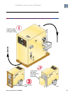
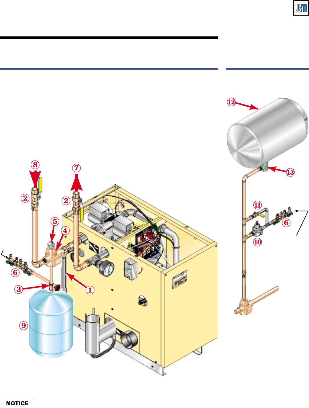
To cold fill
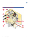
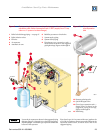
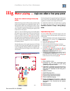
Figure 9 Piping to single-zone system using diaphragm- or bladder-type
expansion tank. Boiler connections are 1" NPT (supply from 1" tee,
return to 1" system circulator flange).
1 Relief valve discharge piping — see page 27
2 Boiler isolation valves
3 Fill valve
4 Air separator
5 Automatic air vent
6 Backflow preventer or check valve
7 System supply piping
8 System return piping
9 Diaphragm-type expansion tank —
always locate as shown in the suggested
piping drawings, Figures 10 through 16
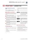
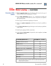
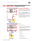
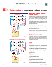
85011
To cold fill
Figure 10 Piping closed-
type expansion
tank
10 Pressure reducing valve
11 Quick-fill bypass valve
12 Closed-type expansion tank —
always locate as shown in the
suggested piping drawings,
Figures 10 through 16
13 Tank fitting
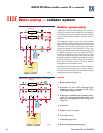
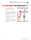
Locate the air separator as shown in the suggested piping
diagram, Figures 11 through 16 on the following pages.
Pipe diaphragm- or bladder-type expansion tanks to the
bottom of the separator.
Pipe closed-type (air in contact with water) tanks to the
top of the air separator. Always connect the fill line to the
expansion tank location, as shown above and in the
suggested piping.