


33Part number 550-141-850/0699
• Installation • Start-Up • Parts • Maintenance
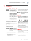
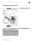
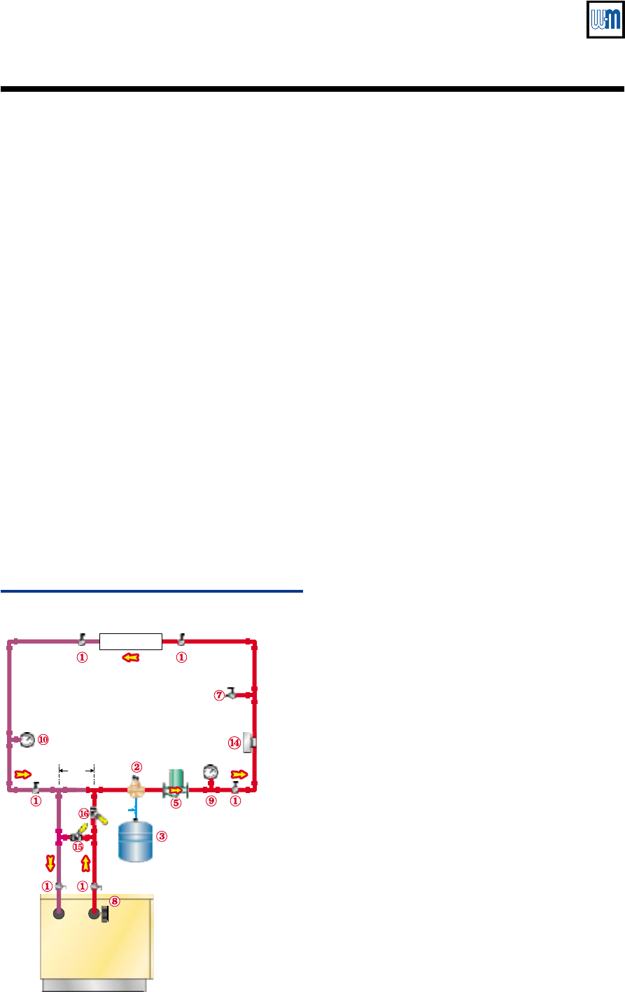
Water piping — single-zone radiant or heat pump systemIIIg
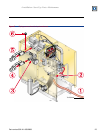
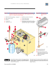
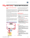
Figure 13 Single-zone radiant heating or
heat pump system
85015a
Load
Cold
water
fill
GV Boiler
12"
max
Legend
1 Boiler isolation valves
2 Automatic air vent (with diaphragm-type
expansion tank), or connect to tank fitting
(closed-type expansion tank).
3 Diaphragm- or bladder-type expansion tank, if
used (For closed-type expansion tank, pipe
from top of air separator to tank fitting as in
Figure 10.)
5 System circulator
7 Hose bibb purge valve
8 Boiler pressure/temperature gauge
9 System supply temperature gauge
10 Return temperature gauge
14 Supply temperature limit control — Set at a
temperature
below
the maximum allowed for
the system or as directed by the system
designer.
15 Balancing valve
16 Balancing valve
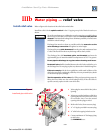
Single-zone radiant heating or heat pump
piping
Radiant heating systems and heat pump systems usually
require system supply water temperatures below 130 °F.
But the boiler outlet water temperature will be at least
150 °F during most operating conditions. So the piping
must include a method of reducing the supply water
temperature to the system.
Figure 13 uses two balancing valves to manually adjust
the supply water temperature. Follow the instructions
below to adjust these valves. Install the supply
temperature limit control (item 14) as shown to protect
the system from overtemperature conditions. Note also
that this piping requires a separate system circulator, as
shown, because of the higher flow rates of radiant and
heat pump systems.
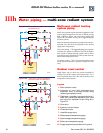
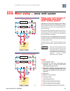
Manual adjustment of the supply temperature is limited
to single-zone systems because multi-zone systems will
cause varying loads, making it unlikely an acceptable valve
setting could be found. See Figure 14a or 14b for multi-
zone systems.
You may also apply the suggested piping of either Figure
14a or 14b if you want automatic supply temperature
regulation or outdoor reset temperature control.
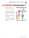
For additional information and alternatives in piping
for radiant heating systems, refer to Weil-McLain
AlumiPex Controls • Pumps • Wiring Design
Guide.
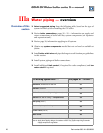
Adjust balancing valves
Use valves 15 and 16 to mix boiler supply water with
system return water, reducing supply water temperature
to the system.
1. Subtract the design system supply temperature from
150 °F. Call this number the temperature
difference
.
2. Open valve 16 and close valve 15.
3. Start the boiler and system.
4. Let the system warm up for about 15 minutes.
5. Note the temperature at gauge 9 (system supply)
and gauge 8 (boiler supply).
6. Slowly close valve 16 while opening valve 15 until
gauge 9 reads lower than gauge 8 by at least the
temperature difference found in step 1.
7. Example: For a design supply temperature of 100 °F,
the temperature difference would be 150 °F
minus 100 °F, or 50 °F. Set the valves until gauge 9
reads at least 50 °F lower than gauge 8.