


Part number 550-141-850/069952
GOLD GV Water boiler series 3 — manualGOLD GV Water boiler series 3 — manual
GOLD GV Water boiler series 3 — manualGOLD GV Water boiler series 3 — manual
GOLD GV Water boiler series 3 — manual
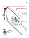
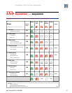
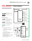
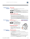
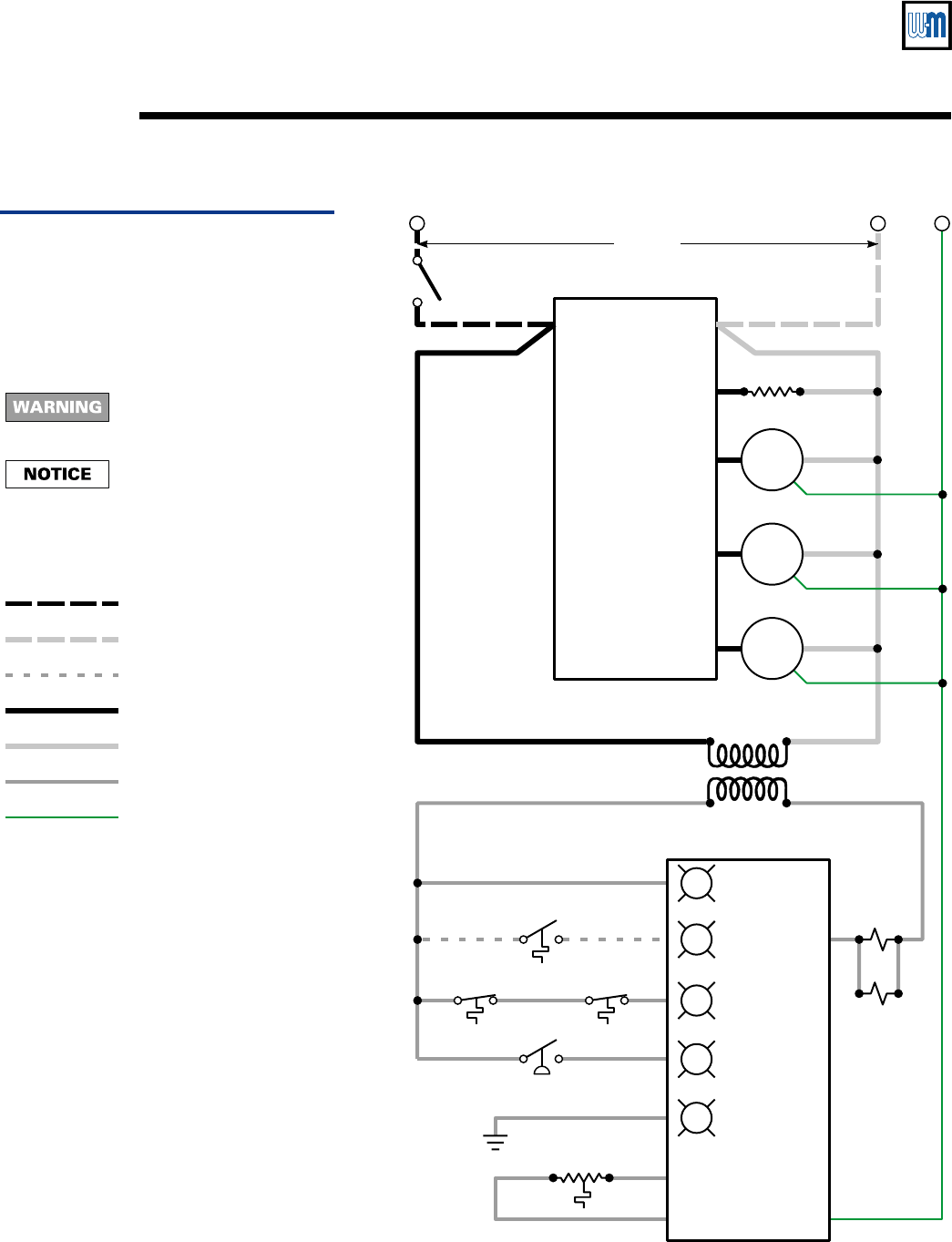
Operation — wiring diagramsIXb
120 VAC
24 VAC
Control module
low voltage
section
Control module
120 VAC
section
Power
Tstat–Circ
Limit
Press switch
Flame
Thermostat (not provided)
Service switch (not provided)
Block temp
limit switch
Blower
motor
System
circulator
Bypass
circulator
Igniter
Water temp
limit switch
Gas valve
Air pressure
switch
Flame
sensor
Water temp sensor
120 VAC Gnd
85030
Electrical shock hazard — can cause severe
injury or death. Disconnect power before
installing or servicing.
1. All wiring must be installed in accordance with:
a. U.S.A. — N.E.C.and any other national, state, or local
code requirements.
b. Canada — C.S.A. C22.1 C.E.C. Part 1 and any other
national, provincial, or local code requirements.
2. All wiring must be:
a. U.S.A. — N.E.C.Class 1.
b. Canada — C.S.A. C22.1 C.E.C. Part 1.
3. If any of the original wire as supplied with the appliance must
be replaced,use type 90 °C or its equivalent.
4. Thermostat anticipator setting (single zone):
0.1 AMP + Gas valve current
5. For multiple zoning, use either zone valves or circulators. Refer
to the component manufacturer's instructions and this manual
for application and wiring suggestions.
6. Refer to control component instructions packed with the
boiler for application information.
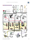
All contacts are shown without power applied.
Notes
Ladder diagram legend
120 VAC hot field wiring
120 VAC neutral field wiring
24 VAC field wiring
120 VAC hot factory wiring
120 VAC neutral factory wiring
Low voltage factory wiring
Ground connectors
Figure 23 Ladder wiring diagram