


Part number 550-141-850/069950
GOLD GV Water boiler series 3 — manualGOLD GV Water boiler series 3 — manual
GOLD GV Water boiler series 3 — manualGOLD GV Water boiler series 3 — manual
GOLD GV Water boiler series 3 — manual
Operation — overviewIXa
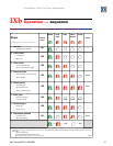
❏ The GCM (control module) is equipped with five indicator lights, used to
show normal and problem situations. See Figure 22 for the normal sequence
of operation of the boiler and control, and the status of the lights at each
stage. For explanation of the lockout conditions of the GCM lights, see
manual Section X, Troubleshooting.
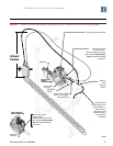
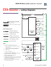
❏ Figure 23 shows the ladder wiring diagram for the GV series 3 boiler.
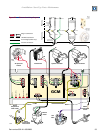
❏ Figure 24 is the schematic wiring diagram, showing the destination of each
of the wire harnesses attached to the control module.
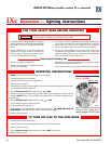
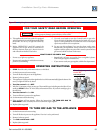
❏ Figure 25 is the Lighting instruction sheet for boilers equipped with
Robertshaw model 7200DERN valves.
❏ Figure 26 is the Lighting instruction sheet for boilers equipped with White-
Rodgers model 36E valves.
Overview of this
section