


4-11
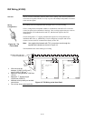
The TIC must be connected to the host panel via RUI cabling. This section explains how
to wire the two together, and how to set up a system with multiple transponders connected
to the same host panel.
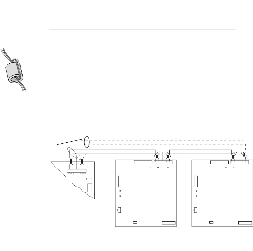
RUI cabling can be accomplished either through Class A or Class B wiring.
Class A wiring allows transponder cabinets to communicate with the FACP even in the
event of an open circuit somewhere in the loop. Class A wiring requires that two wires are
routed from the CPU motherboard to each TIC, and then back again to the CPU
motherboard.
Class B wiring allows “T” tapping, and therefore requires less wiring distance per
installation than Class A. Additionally, Class B wiring does not require end-of-line
resistors, because each TIC communicates directly to the CPU.
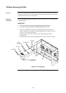
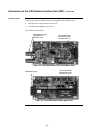
Note: Use supplied ferrite beads with TICs. Loop wires once through the
supplied ferrite bead(s) as shown in Figure 4-4.
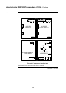
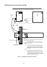
The illustration below shows both types of wiring.
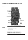
TRANSPONDER INTERFACE
ASSY 566-094
MSB
LSB
LED1
ADDRESS
LED3
PRI
B+ B- SHLDA+A-
SEC
RUI
SHLD
LED4 LED5
LED2
P1
P2 P3
RUI
P9
P1
123
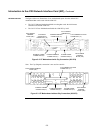
TRANSPONDER INTERFACE
ASSY 566-094
MSB
LSB
LED1
ADDRESS
LED3
PRI SEC
RUI
SHLD
LED4 LED5
LED2
P1
P2
Figure 4-5. TIC Wiring to the Host Panel
Continued on next page
RUI Wiring (4100U)
Overview
Wiring
Configurations
Figure 4-4. The
Ferrite Bead
DASHED LINES ARE FOR
CLASS A OPERATION
• Wire size must be
between 18 AWG (0.8231 mm
2
)
and 12 AWG (3.309 mm
2
).
• Maximum wiring distance: 2,500 feet
(762 m).
• Maximum “T” tapping length:
10,000 feet (3,048 m).
• Maintain correct polarity on terminal
connections.
• Do not loop wires under terminals.
CPU
MOTHERBOARD
566-227