


2-14
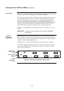
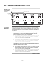
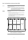
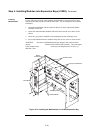
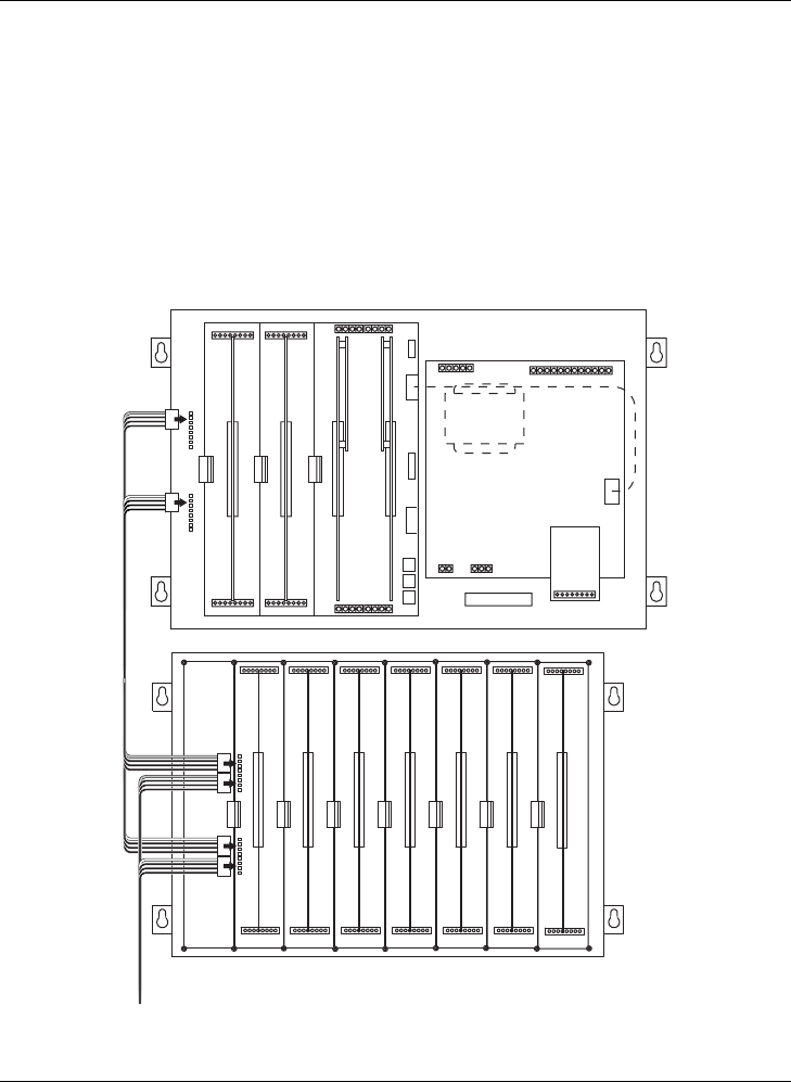
2. Connect the other end of the harness to the leftmost motherboard in the next bay,
as described below. Make sure to route the wiring on the left side of the bay.
• Insert the harness connector with the blue wire into the P2 connector. Note
that the P2 connector has eight pins. Insert the harness connector on either
the top four pins or the bottom four pins, not in the middle.
• Insert the harness connector with the white wire into the P3 connector. Note
that the P3 connector has eight pins. Insert the harness connector on either
the top four pins or the bottom four pins, not in the middle.
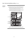
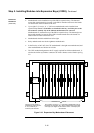
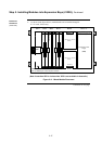
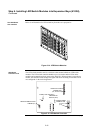
Figure 2-8. Power and Communication Wiring for Motherboards
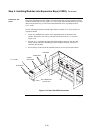
Step 4. Interconnecting Modules and Bays, Continued
Connecting to
Motherboards
(continued)
Connector with
Blue Wire Goes
to P2
Connector with
White Wire Goes
to P3
733-525 Harness