


6-7
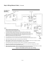
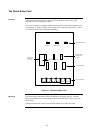
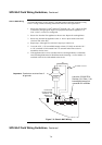
The Alarm Relay Card mounts on, and is driven by, the SPS. It has 3 relays each
providing one set of voltage-free contacts.
The relays are able to be configured under custom control, but the default operation is for
system status, i.e. Fault (Trouble), Isolate (Supervisory), and Alarm, respectively. These
are commonly used to drive the Brigade signalling.
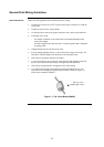
TROUBLE SUPERVISORY ALARM
F3 F2 F1
p
3
p
2
p
1
LD1 LD2 LD3
Fault
(Trouble)
Isolate
(Supervisory)
Alarm
10 Way FRC
connects to P7
on SPS
Energised Relay LEDs
Energised Relay LEDs
Normally Closed/
Normally Open
Jumpers
3A, 5 x 15mm Fuses
TB1 Terminal Block
Figure 6-1. The Alarm Relay Card
The Alarm Relay Card mounts on the SPS adjacent to the largest relay K3. With the
power disconnected, fit the card using the 3 plastic stand-offs and one Torx screw with
plastic sleeve.
Connect P4 on the relay card to P7 on the SPS with the 10 way FRC provided.
The Alarm Relay Card
Overview
Mounting