


2-20
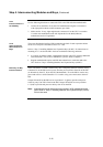
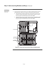
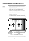
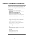
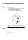
The LED/switch user interface consists of a variety of modules, mounted to the front of
an expansion bay, which are configured via the 4100 Programmer. Each display module
contains between 8 and 24 switches and LEDs, each one separately configurable.
User interface functionality is driven by the 64/64 LED/Switch Controller Card, which
mounts behind two of the display modules (typically in positions 3 and 4). The varieties
of modules are as follows:
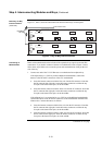
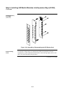
• 4100-1288 LED/Switch Controller Card with mounting plate.
• 4100-1289 LED/Switch Controller Card (no mounting plate; mounts on extra
space of 4100-1288).
• 4100-1280 8-Switch/8-LED Display Card. With red LEDs.
• 4100-1281 8-Switch/8-LED Display Card. With yellow LEDs.
• 4100-1282 8-Switch/16-LED Display Card. With one red and one yellow LED
per switch.
• 4100-1283 8-Switch/16-LED Display Card. With two yellow LEDs per switch.
• 4100-1284 8-Switch/16-LED Display Card. With one red and one green LED
per switch.
• 4100-1285 16-Switch/16-LED Display Card. With red LEDs.
• 4100-1286 Hands Off Auto (HOA) Switch Display Card. Provides 24 switches
and 24 LEDs. The HOA uses an overlay to group every 3 switches together,
denoting on, off, and automatic control of smoke control components. For every
group of 3 switches, there are 3 LEDs (green-red-green).
• 4100-1287 24-Switch/24-LED Display Card. With red LEDs.
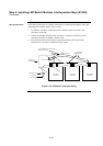
• 4100-1279 2” Blank display cover module to cover empty front panel space
• 4100-1294 Slide-In Label Kit - one per 4100U cabinet
• 4100-1276 8-Pluggable LEDs with 8 red LEDs
• 4100-1277 16-Pluggable LEDs with alternating red and yellow LEDs
• 4100-1278. 16-Switch/16-LED with alternating red and yellow LEDs, one per
switch
• 4100-1295 Hands Off Auto (HOA) switch display card. Provides 24 switches
and 24 red LEDs.
• 4100-1296 8-Switch/16 LED Display Card. With one green and one yellow
LED per switch.
• 4100-9843 Pluggable LED Kit, 8 Yellow LEDs
• 4100-9844 Pluggable LED Kit, 8 Green LEDs
• 4100-9845 Pluggable LED Kit, 8 Red LEDs
• ME0456 Fan Control Module
Continued on next page
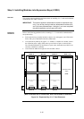
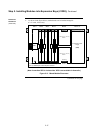
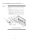
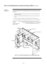
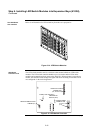
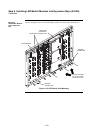
Step 6. Installing LED/Switch Modules into Expansion Bays (4100U)
Overview