


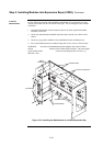
2-15
This section contains guidelines and instructions on installing 4”x 5” cards and traditional
motherboards into 4100U card bays.
IMPORTANT: This section applies to aftermarket modules for expansion bays
only. If you do not need to install any aftermarket modules at all,
and if you have followed Steps 1 through 6, you have completed
the panel installation and can apply AC power.
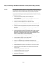
Refer to the following guidelines before mounting 4” x 5” cards and/or motherboards to
an expansion bay.
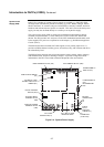
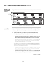
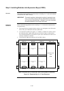
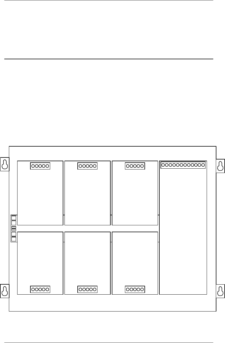
• Each expansion bay assembly includes a chassis, two end supports, one LED/switch
frame, and a power distribution interface (PDI) board.
• An expansion bay holds up to eight 4” x 5” modules. A double-size module, such as
the expansion power supply (XPS), takes up two blocks of space as shown below.
The Australian SPS takes up four blocks of space (note, the double sized XPS is not
currently available for Australia).
• Cards should be added from right to left if an XSPS is fitted.
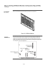
Power Distribution Interface (PDI)
Expansion Power
Supply
(XPS)
I/O Wiring I/O Wiring I/O Wiring
I/O Wiring I/O Wiring I/O Wiring
I/O Wiring
Block A Block C
Block B Block D
Block E Slots 7 + 8
Block F
4" (102 mm) x 5" (127 mm)
Module
4" (102 mm) x 5" (127 mm)
Module
4" (102 mm) x 5" (127 mm)
Module
4" (102 mm) x 5" (127 mm)
Module
4" (102 mm) x 5" (127 mm)
Module
4" (102 mm) x 5" (127 mm)
Module
(Note. Australian SPS is 4 slots wide. XPS is not available in Australia.)
Figure 2-9. Expansion Bay 4”x 5” Card Placement
Continued on next page
Step 5. Installing Modules into Expansion Bays (4100U)
Overview
Placement
Guidelines