


8-6
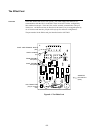
Configuring the card consists of selecting the shield tie point, and setting the device
address..
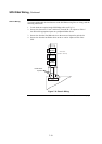
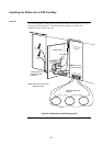
If a shielded cable is used, connect the cable shield to the dedicated terminal on TB1 and
use jumper port (P1) to select where the shield will be tied.
• Position 1 - 2 connects the shield to 0 V.
• Position 2 - 3 connects the shield to Earth.
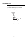
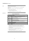
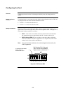
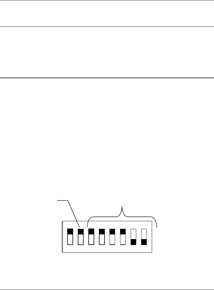
The device address is set on DIP switch SW1, which is a bank of eight switches (see
figure below). From left to right, these switches are designated as SW1-1 through SW1-8.
The function of these switches is as follows:
• SW1-1. This switch sets the baud rate for the internal 4100 communications
line running between the card and the 4100 CPU. Set this switch to ON.
• SW1-2 through SW1-8. These switches set the card’s address within the
4100 FACP. Refer to the table in Appendix A for a complete list of the switch
settings for all of the possible card addresses.
Note: You must set these switches to the value assigned to the card by the
4100 Programmer.
1
8
7
6
5
4
3
2
Figure 8-4. DIP Switch SW1
Configuring the Card
Overview
Setting the Shield
Tie Point
Setting the Address
ON
OFF
Dip Switches SW1-2 through
SW1-8 set the Card Address.
Figure shows an Address of 3.
4100 Comm. Baud Rate.
Switch (SW1-1)
Must Be Set to ON