


xiv
Figure 1-1. Standalone 4100U System........................................................... 3
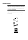
Figure 1-2. MINIPLEX 4100U System ............................................................ 5
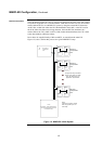
Figure 1-3. Hub/Ring Configuration ................................................................6
Figure 1-4. Interconnected Loop Configuration............................................... 7
Figure 2-1. Master (CPU) Motherboard (566-227).......................................2-3
Figure 2-2. Master Controller Daughter Card (566-149)..............................2-4
Figure 2-3. Operator Interface......................................................................2-6
Figure 2-4. System Power Supply................................................................2-7
Figure 2-5. The Power Distribution Interface (PDI)......................................2-8
Figure 2-6. Bracket Mounting.......................................................................2-9
Figure 2-7. Bay-to-Bay Interconnections....................................................2-13
Figure 2-8. Power and Communication Wiring for Motherboards..............2-14
Figure 2-9. Expansion Bay 4”x 5” Card Placement....................................2-15
Figure 2-10. Expansion Bay Motherboard Placement .................................2-16
Figure 2-11. Mixed Module Placement ........................................................2-17
Figure 2-12. Slave Card/PDI Connection.....................................................2-18
Figure 2-13. Installing the Motherboard in a 4100U Expansion Bay............2-19
Figure 2-14. LED/Switch Modules................................................................2-21
Figure 2-15. LED/Switch Controller..............................................................2-21
Figure 2-16. LED/Switch Card Mounting......................................................2-23
Figure 2-17. Controller Card Mounting.........................................................2-24
Figure 2-18. Assembling / Disassembling the LED Display Card................2-25
Figure 2-19. LED/Switch Controller Wiring ..................................................2-26
Figure 2-20. Terminal Block Utility Module Mounting ..................................2-27
Figure 3-1. MINIPLEX System Design.......................................................3-31
Figure 3-2. The Remote Unit Interface Card..............................................3-32
Figure 3-3. The RIC II Card........................................................................3-33
Figure 3-4. Installing the RUI Motherboard in the CPU Bay ......................3-35
Figure 3-5. Installing the RIC II Motherboard into a 4100 Expansion Bay.3-36
Figure 3-6. Power and Communication Wiring for the Transponder
Cabinet (4100) .........................................................................3-38
Figure 3-7. MINIPLEX Wiring.....................................................................3-40
Figure 4-1. Transponder Interface Cards.....................................................4-4
Figure 4-2. TIC Mounting .............................................................................4-9
Figure 4-3. Transponder Cabinet Interconnections....................................4-10
Figure 4-5. TIC Wiring to the Host Panel ...................................................4-11
Figure 5-1. 4100-6014 Network Interface Card............................................5-4
Figure 5-2. UT Motherboard with City Connection (565-274)......................5-5
Figure 5-3. UT Motherboard without City Connection (565-275).................5-5
Figure 5-4. The 4100/4120-0143 Fiber-Optic Media Card...........................5-6
Figure 5-5. The 4100/4120-0142 Wired Media Card ...................................5-6
Figure 5-6. Media Card Mounting ................................................................5-9
Figure 5-7. Installing the Daughter Card....................................................5-10
Figure 5-8. The Transient Suppressor .......................................................5-12
Figure 5-9. Fiber Wiring..............................................................................5-13
Figure 5-10. Coupler Wiring .........................................................................5-15
Figure 5-11. Wired Media Interconnections Between 4100U Motherboards5-16
Figure 5-12. Wired Media, Style 7 Wiring ....................................................5-17
Figure 5-13. Fiber Optic, Style 7 Wiring.......................................................5-18
Figure 5-14. Wired Media and Fiber Optic, Style 7 Wiring...........................5-19
Figure 6-1. The Alarm Relay Card ...............................................................6-7
Figure 7-1. The Ferrite Bead (SX0005)........................................................7-2
Figure 7-2. Class A NAC Wiring...................................................................7-4
Figure 7-3. Class B Wiring ...........................................................................7-5
Figure 7-4. Auxiliary Power Wiring...............................................................7-9
Figure 7-5. Auxiliary Relay & Alarm Relay Card Relays............................7-11
Figure 7-6. Class A Wiring .........................................................................7-13
Figure 7-7. Class B Wiring .........................................................................7-14
Figure 8-1. The IDNet Card..........................................................................8-2
List of Figures